Fluid dynamic bearing unit and disk drive device including the same

Inactive Publication Date: 2010-11-04
ALPHANA TECH CO LTD
View PDF6 Cites 15 Cited by
  • Summary
  • Abstract
  • Description
  • Claims
  • Application Information

AI Technical Summary

Benefits of technology

[0033]This invention has the following advantages. The lubricant is injected into the fluid dynamic bearing unit simultaneously via the clearances of the first and second capillary seals. Therefore, the injection of the lubricant into the fluid dynamic bearing unit can be easily perfor

Problems solved by technology

In a disk drive device, higher-speed rotation of a recording disk causes greater unwanted vibration of a magnetic head which disturbs the tracing of a recording track by the magnetic head.
The lubricant can not easily move into a narrow clearance in

Method used


Image

  • Fluid dynamic bearing unit and disk drive device including the same
  • Fluid dynamic bearing unit and disk drive device including the same
  • Fluid dynamic bearing unit and disk drive device including the same

Examples


Embodiment Construction

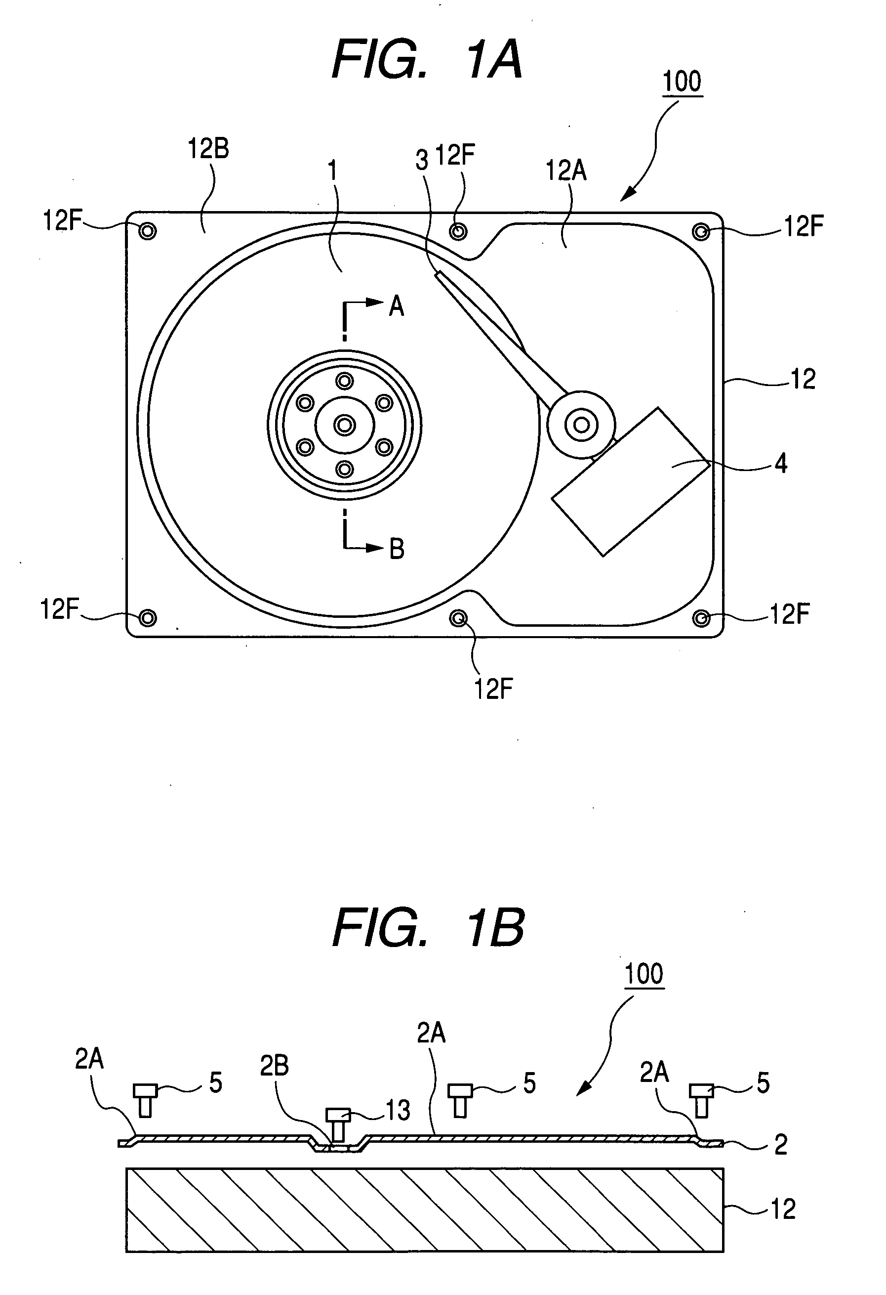
[0050]With reference to FIGS. 1A, 1B, and 2, a disk drive device 100 in an embodiment of this invention includes a top cover 2, a base 12, and a fluid dynamic bearing unit (FDB) 50.

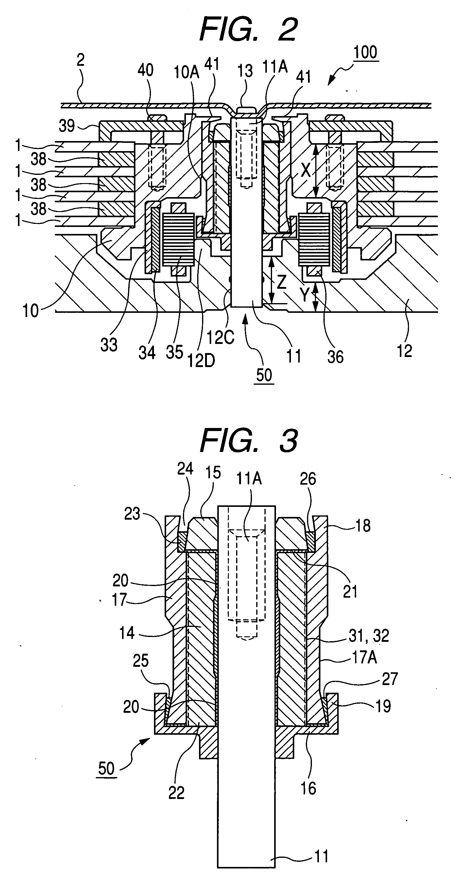
[0051]The FDB 50 takes an approximately cylindrical body, and includes a columnar shaft 11 coaxial with and centered at the body. One end (the lower end in FIG. 2) of the shaft 11 is fixed to the base 12. The other end (the upper end in FIG. 2) of the shaft 11 is formed with an axially-extending threaded hole 11A. The other end of the shaft 11 is fixed to the top cover 2 by a screw 13 having a head in contact with the top cover 2 and extending into the threaded hole 11A to engage with the shaft 11.

[0052]As best shown in FIG. 3, the FDB 50 includes the shaft 11, a first sleeve 14, a first flange 15, a second flange 16, a second sleeve 17, a first annular member 18, and a second annular member 19 substantially coaxial with each other. The first and second sleeves 14 and 17 are approximately cylindrical. The...


PUM


Abstract

A first sleeve rotatably extends around a shaft. First and second flanges are fixed to the shaft. A second sleeve extending around the first sleeve is fixed thereto. A first annular member fixed to the second sleeve surrounds the first flange. A second annular member fixed to the second flange surrounds a portion of the second sleeve. A first capillary seal includes a clearance between the first flange and the first annular member. A second capillary seal includes a clearance between the second annular member and the second sleeve. Lubricant is provided in the clearances in the first and second capillary seals. The second annular member and the second sleeve are designed so that the lubricant in the clearance in the second capillary seal can be viewed from a point in a radial position which is outward of the second sleeve as seen in an axial direction.

Description

BACKGROUND OF THE INVENTION[0001]1. Field of the Invention[0002]This invention relates to a fluid dynamic bearing unit and a drive device for a recording disk. In addition, this invention relates to a method of manufacturing a fluid dynamic bearing unit.[0003]2. Description of the Related Art[0004]In recent years, disk drive devices such as HDDs have included fluid dynamic bearing units (abbreviated to FDBs) to enhance disk drive performances. Generally, a disk drive device capable of rotating a recording disk at a higher speed is desired. In a conventional disk drive device for magnetically recording data on a recording disk, the speed of rotation of the disk is 3600 min−1. Recent disk drive devices rotate recording disks at a speed of 5400 min−1 or 7200 min−1.[0005]In a disk drive device, higher-speed rotation of a recording disk causes greater unwanted vibration of a magnetic head which disturbs the tracing of a recording track by the magnetic head. A known disk drive structure d...

Claims


Application Information

Patent Timeline
IPC IPC(8): G11B15/64B21D53/10
CPCG11B5/4813G11B33/123G11B19/2036Y10T29/49639F16C17/107F16C33/103F16C2370/12F16C33/745F16C32/0659G11B19/2018
Inventor SUGIKI, RYUSUKE
Owner ALPHANA TECH CO LTD
Why Eureka
Try Eureka