
Solar-charged warning device

a solar energy and warning device technology, applied in secondary cells servicing/maintenance, lighting and heating apparatus, lighting support devices, etc., can solve the problems of occupying space and the location of batteries, unable to recognize helmets in the dark, and warning devices that might not function properly, etc., to achieve the effect of ensuring the safety of users

Inactive Publication Date: 2010-11-04
TRANS CHIEF +1
View PDF6 Cites 12 Cited by
  • Summary
  • Abstract
  • Description
  • Claims
  • Application Information

AI Technical Summary

Benefits of technology

[0004]Therefore, the object of the present invention is to provide a warning device which is automatically charged by the solar energy so as to eliminate the inconvenience of battery replacement.
[0005]Another object of the present invention is to provide a warning device with voltage amplifier circuit, so that the power unit of the warning device can be configured to have a smaller voltage potential, thereby the occupied volume thereof can be reduced.
[0007]Accordingly, the present invention utilizes the solar photovoltaic panel to absorb the solar energy and transform thereof into the electricity, which is then used to charge the secondary battery, so that as the light source is absent, the secondary battery can be discharged to drive the light-emitting element to shine. Therefore, even the helmet is used in a dark environment, the light-emitting element also can shine to provide the warning effect and secure the user's safety.

Problems solved by technology

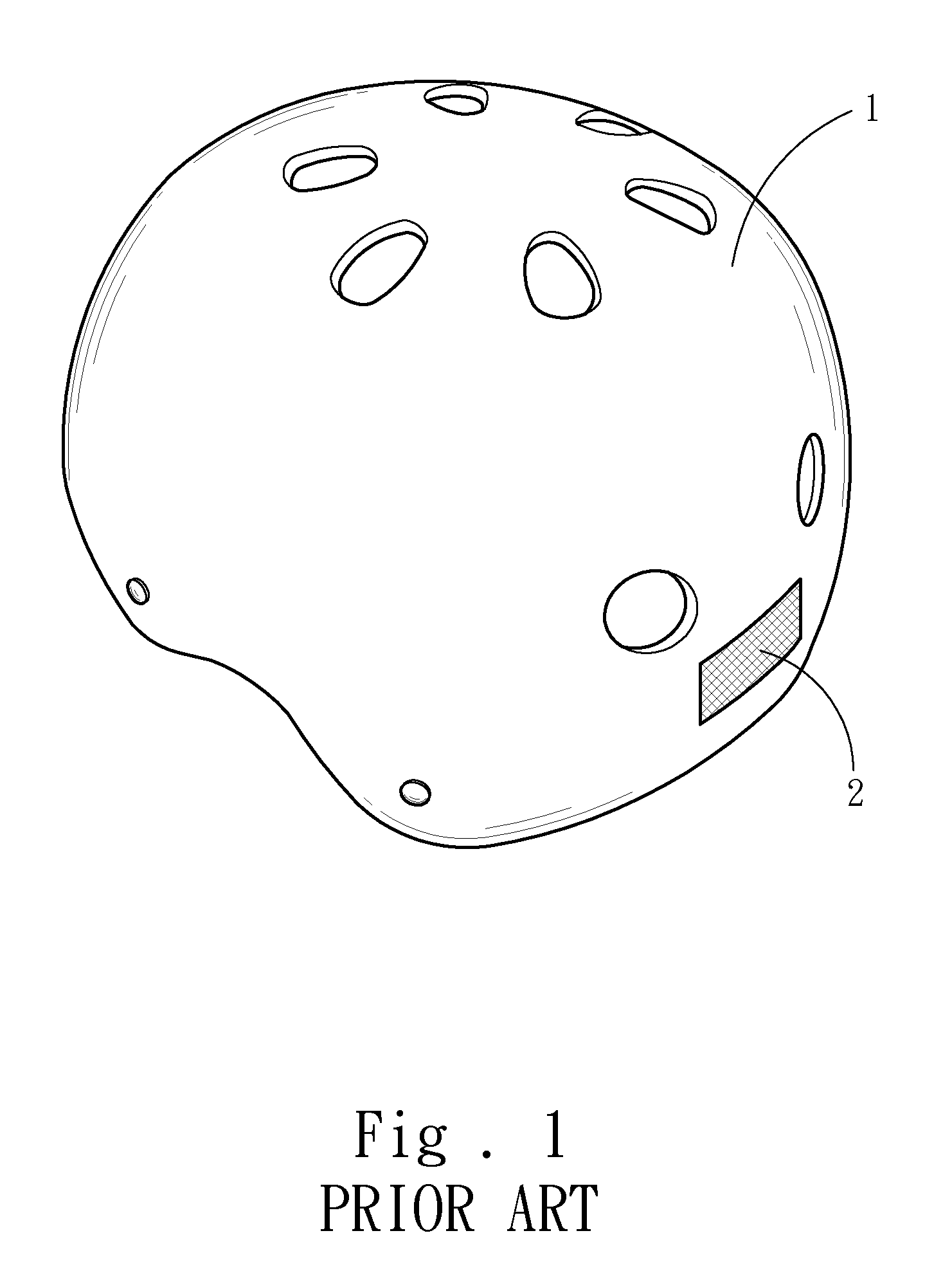
However, since the reflector only radiates light without the light source, it is difficult to recognize the helmet 1 in the dark.
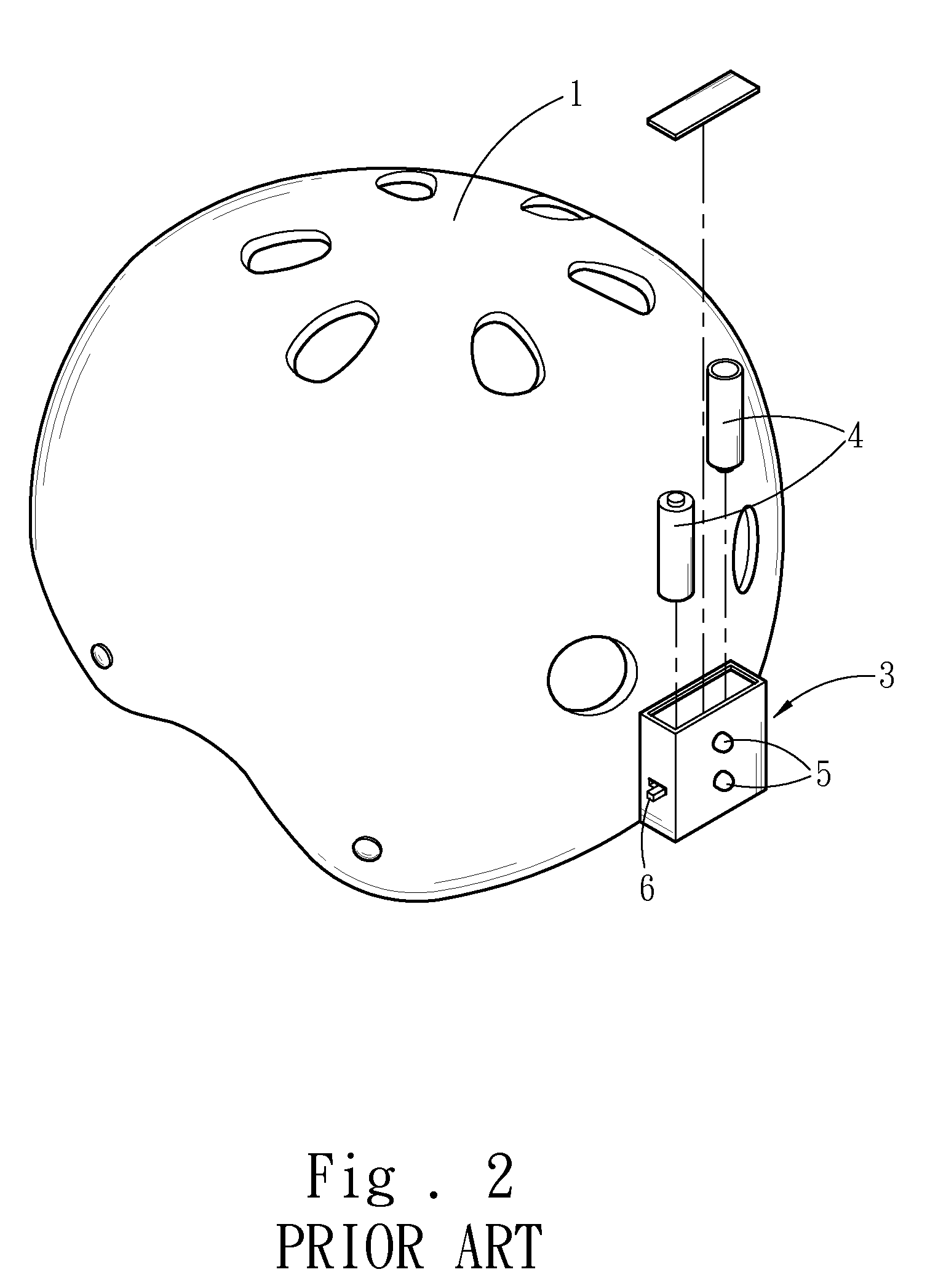
However, since the electricity provided by the batteries 4 is easily exhausted by the light source 5 in a short period of time, the user has to replace the batteries 4 very often, so that as the batteries are not replaced in time, the warning device might not function properly.
Besides, for providing sufficient output voltage, the batteries 4 have to connect in series, so that the occupied space and the location of the batteries are both limited.

Method used


Image

  • Solar-charged warning device
  • Solar-charged warning device
  • Solar-charged warning device

Examples


Embodiment Construction

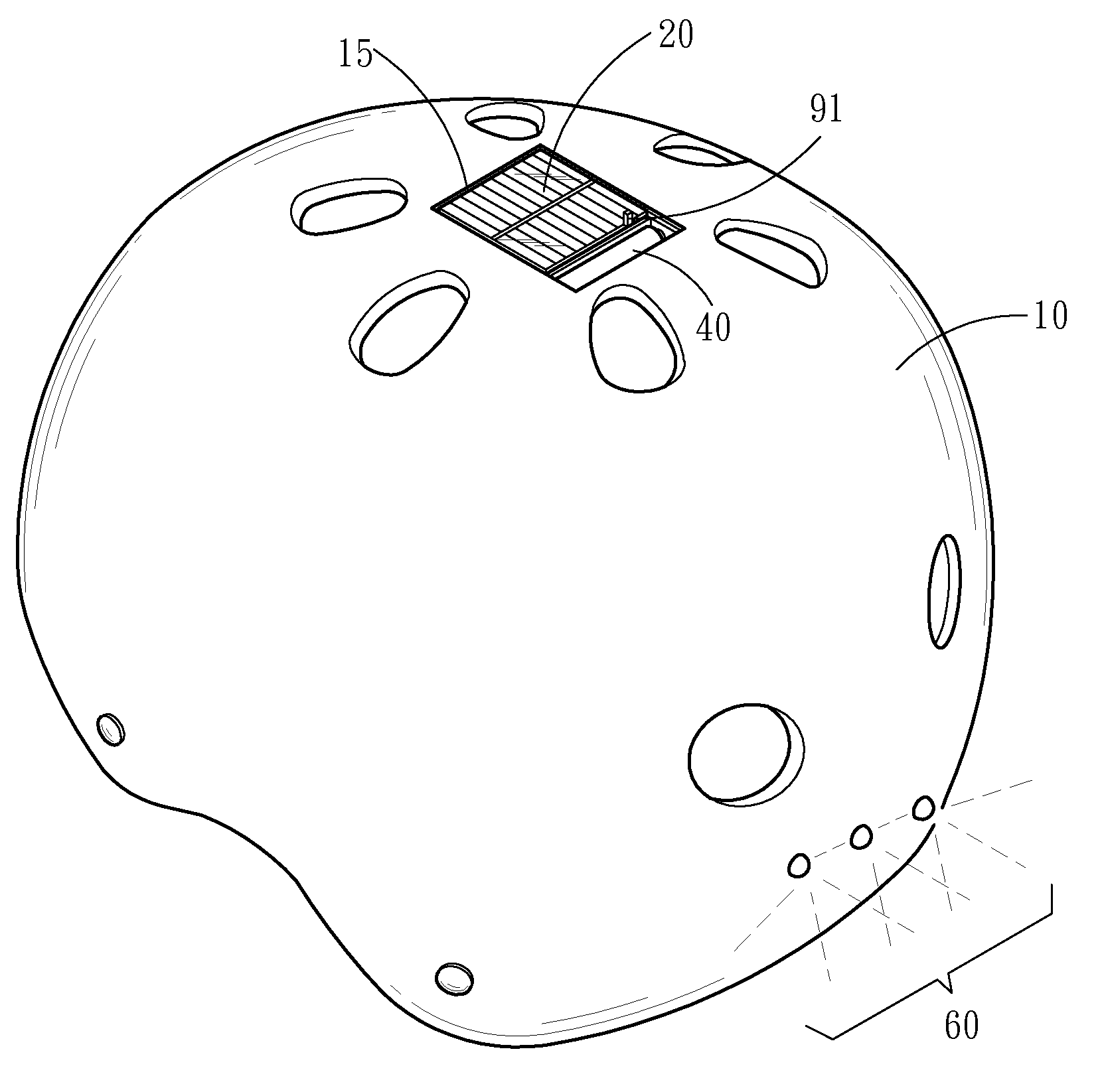
[0014]Please refer to FIG. 3, FIG. 4 and FIG. 5. The present invention is related to a solar-charged warning device which is mounted on a helmet 10. The solar-charged warning device includes a solar photovoltaic panel 20, a charge / discharge circuit 30, a secondary battery 40, a voltage amplifier circuit 50 and at least one light-emitting element 60, wherein the solar photovoltaic panel 20 is mounted on the outer surface of the helmet 10 to absorb the light and transform thereof into electricity. Here, a transparent sheet 15 also can be provided on the solar photovoltaic panel 20 to protect the solar photovoltaic panel 20.

[0015]The solar photovoltaic panel 20 is electrically connected to the charge / discharge circuit 30, and the secondary battery 40 is electrically connected to the charge / discharge circuit 30 for receiving and storing the electricity produced from the solar photovoltaic panel 20. Here, the secondary battery 40 can be selected from a Li battery, a Ni—H battery or a sto...


PUM


Abstract

The present invention discloses a solar-charged warning device, mounted on a helmet, including at least one light-emitting element, a solar photovoltaic panel, a voltage amplifier circuit, a sensor circuit, a charge / discharge circuit, and a secondary battery. The solar photovoltaic panel mounted on the helmet is used to absorb the solar energy and transform thereof into the electricity, and then the electricity is inputted into the sensor circuit, the charge / discharge circuit and the secondary battery, for storing the electricity in the secondary battery. When there needs the electricity, it can be discharged by the charge / discharge circuit and then amplified by the voltage amplifier circuit to reach the required voltage, so as to drive the light-emitting element to shine. When there exists the light source, the secondary battery will be charged. When in the dark, the electricity stored in the secondary battery will be discharged to drive the light-emitting element to shine.

Description

FIELD OF THE INVENTION[0001]The present invention is related to a warning device, and more particularly to a warning device for a helmet of a rider.BACKGROUND OF THE INVENTION[0002]Please refer to FIG. 1. For riders, the helmet 1 is widely used since it can reduce the damage as the traffic accidence occurs. Conventionally, for enhancing the visibility of the helmet 1 at night, a reflector 2 is mounted thereon, so that the reflection light from the reflector 2 can recognize the position of the helmet 1. However, since the reflector only radiates light without the light source, it is difficult to recognize the helmet 1 in the dark.[0003]Further, please refer to FIG. 2, in which for increasing the warning effect, a warning device 3 is mounted on the helmet 1. The warning device 3 includes two batteries 4 and at least one light source 5, wherein the light source 5 is powered by the two batteries 4, so that even in the dark, the warning effect still can be maintained. In addition, a swit...

Claims


Application Information

Patent Timeline
IPC IPC(8): F21V21/084F21L4/00H01M10/46
CPCH01M10/465A42B3/044Y02E60/10
Inventor HUANG, MEI-FENG
Owner TRANS CHIEF
Learn More