Eureka AIR delivers breakthrough ideas for toughest innovation challenges, trusted by R&D personnel around the world.

Image forming apparatus and image forming method

Inactive Publication Date: 2010-11-04
SEIKO EPSON CORP
View PDF5 Cites 6 Cited by
  • Summary
  • Abstract
  • Description
  • Claims
  • Application Information

AI Technical Summary

Benefits of technology

[0010]In the image forming apparatus and image forming method according to the invention, the effective circumference of the transfer roller is set to an integral multiple or an approximate integral multiple of the circumference of the latent image bearing drum, which lends cyclicity to image unevenness caused by fluctuations in the load at the concaved portion, which enables those fluctuations to be predicted. This in turn makes it possible to respond to such fluctuations in the various types of controls that are carried out.
[0011]In addition, detecting the rotation position of the transfer roller in which the image unevenness actually occurs using the position detection portion makes it possible to determine the gripping position of the transfer roller, the position of the transfer roller itself, and so on, enabling favorable control to be carried out. Furthermore, the accuracy of image unevenness suppression can be increased by detecting the rotation position of the latent image bearing drum using the position detection portion and controlling the movement velocity of the latent image bearing drum so that the rotation position of the transfer roller matches the reference.

Problems solved by technology

When a roller having a concaved portion is used, fluctuations arising due to fluctuations in the load at the concaved portion, rotational unevenness arising due to eccentricity or wobbles in the roller, and so on are transmitted to the photosensitive member or the like, resulting in printing skew at the primary transfer portion of the photosensitive member, the exposure unit, or the like.
In the case where this printing skew is not cyclic, it is difficult to properly control the alignment between the different colors, the alignment with respect to the paper, and so on.

Method used


Image

  • Image forming apparatus and image forming method
  • Image forming apparatus and image forming method
  • Image forming apparatus and image forming method

Examples


Embodiment Construction

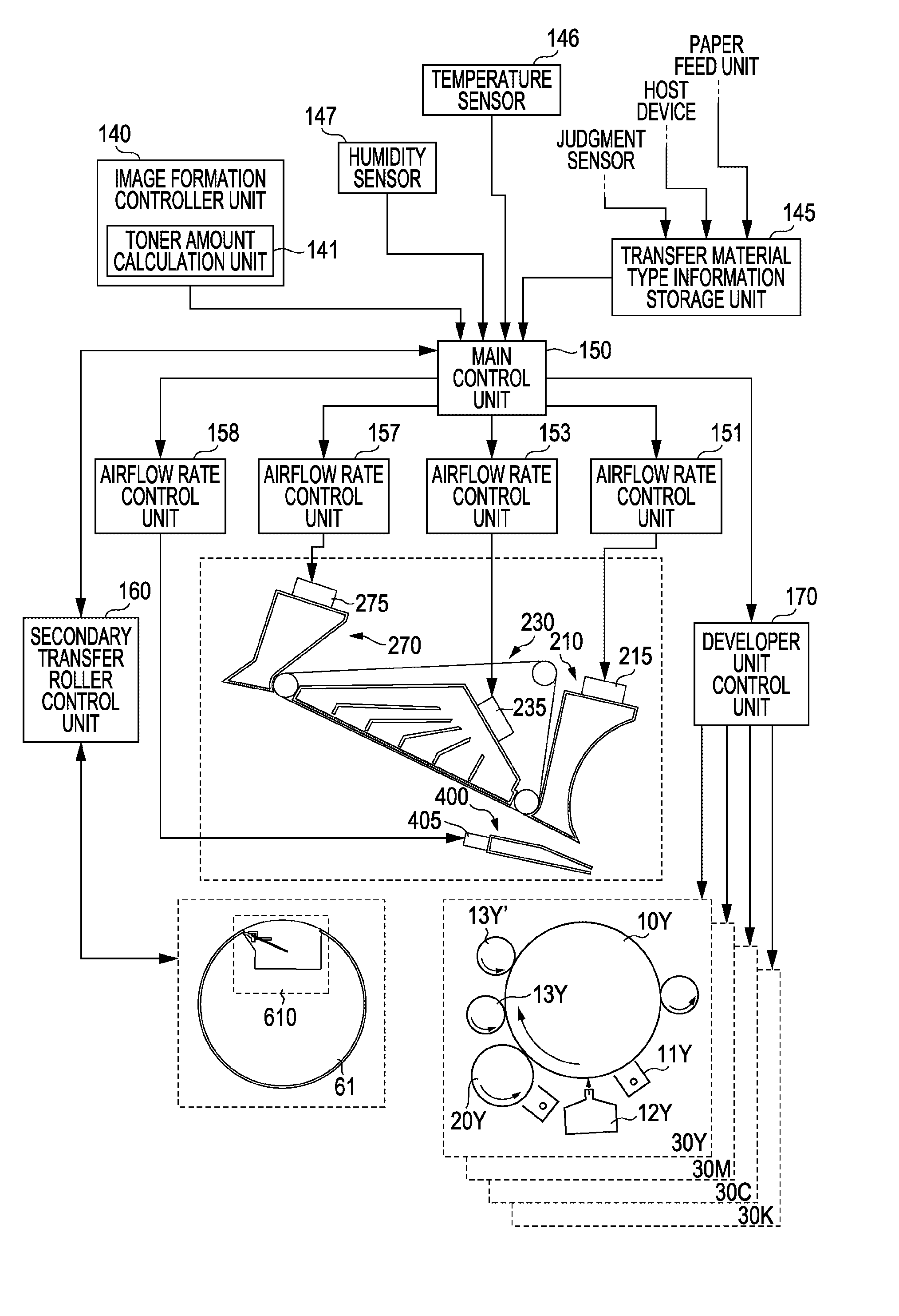
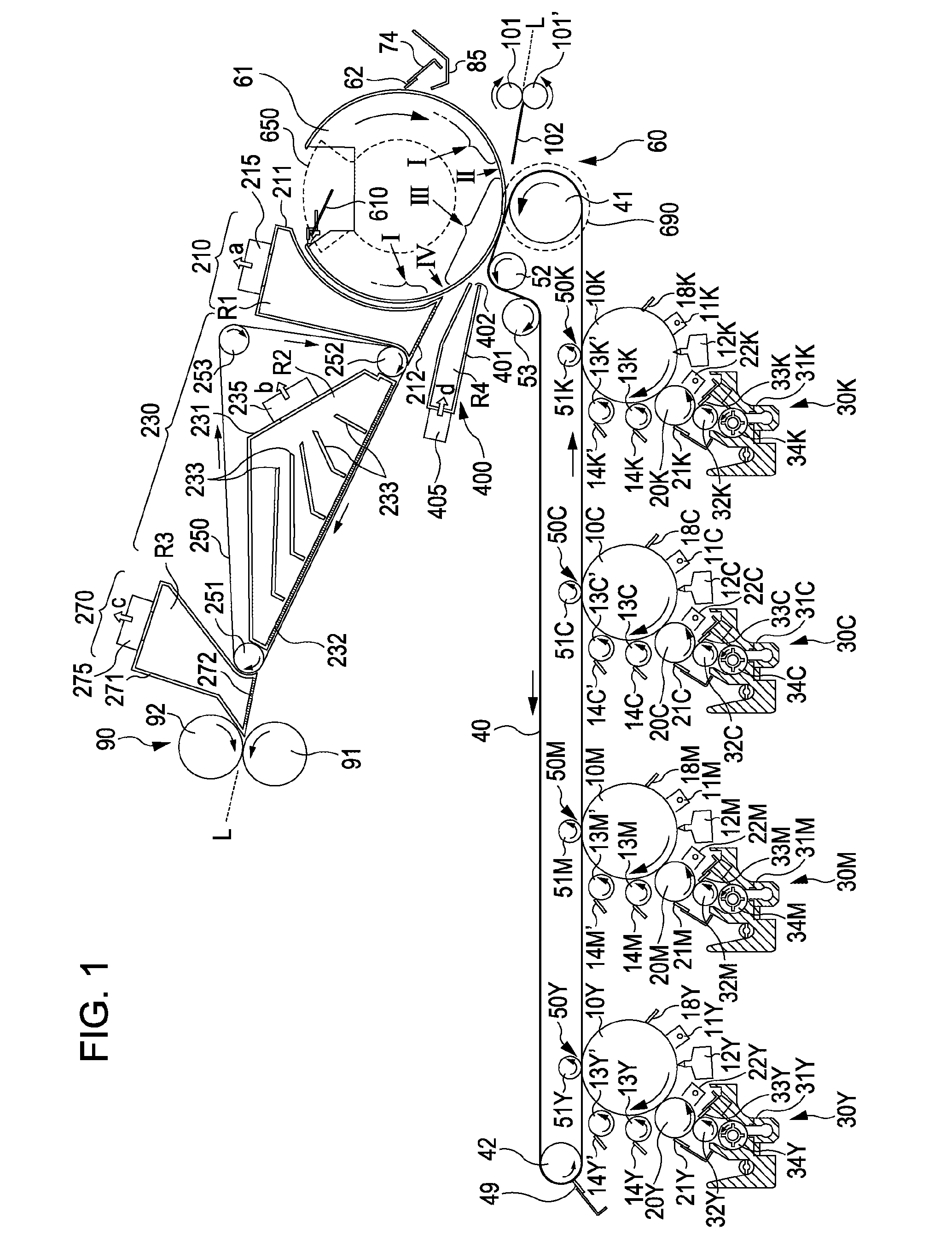
[0033]Embodiments of the invention will now be described with reference to the drawings. FIG. 1 is a diagram illustrating the primary elements of which an image forming apparatus according to an embodiment of the invention. Image forming units of respective colors are disposed in the central portion of the image forming apparatus. Developer units 30Y, 30M, 30C, and 30K are disposed in the lower portion of the image forming apparatus, and elements such as a transfer belt 40, a secondary transfer portion (secondary transfer unit) 60, a fixing unit 90, and so on are disposed in the upper portion of the image forming apparatus. In particular, the fixing unit 90 is disposed above the transfer belt 40, thereby making it possible to reduce the installation footprint of the image forming apparatus as a whole. In this embodiment, the configuration is such that a transfer material such as paper that has undergone a secondary transfer in the secondary transfer unit 60 is pulled by a transfer m...


PUM


Abstract

An image forming apparatus including a latent image bearing drum on which a latent image is formed, an exposure unit that exposes the latent image bearing drum, a developer unit that develops the latent image formed on the latent image bearing drum, a transfer medium onto which the image developed by the developer unit is transferred, and a transfer roller that transfers the image from the transfer medium to the transfer material, the transfer roller having a concaved portion extending in the axial direction and a support portion disposed on the outer circumference of the roller that supports the transfer material, where the outer circumference of the transfer roller being an integral multiple or an approximate integral multiple of the circumference of the latent image bearing drum.

Description

BACKGROUND OF THE INVENTION[0001]The entire disclosures of Japanese Patent Application No. 2009-110984, filed Apr. 30, 2009 is expressly incorporated herein by reference.[0002]1. Technical Field[0003]The present invention relates to an image forming apparatus and image forming method. More specifically, the present invention relates to an apparatus and method that form an image by developing a latent image formed upon a photosensitive member using a liquid developer including of toner and a liquid carrier, transferring the resulting developer onto a medium such as recording paper, and fusing and fixing the toner image that has been transferred onto the medium.[0004]2. Related Art[0005]Various wet-type image forming apparatuses are known in the art that develop latent images using a high-viscosity liquid developer in which is dispersed toner including of solid components within a liquid carrier, thereby visualizing electrostatic latent images. The developer used in these wet-type ima...

Claims


Application Information

Patent Timeline
IPC IPC(8): G03G15/14
CPCG03G15/161G03G15/1655G03G15/757G03G15/1605G03G2215/1614G03G2215/1619G03G2215/00075
Inventor CHIBA, SATOSHIIKUMA, KEN
Owner SEIKO EPSON CORP
Why Eureka
Eureka Blog
Learn More