Rechargeable battery

Active Publication Date: 2010-11-04
ROBERT BOSCH GMBH +1
View PDF62 Cites 133 Cited by
  • Summary
  • Abstract
  • Description
  • Claims
  • Application Information

AI Technical Summary

Benefits of technology

[0008]The described technology of embodiments provid

Problems solved by technology

When excessive heat is generated in the rechargeable battery or when the internal pressure increases as an electrolyte solution in the rechargeable battery is decomposed, the battery may explode or catch fire.
In part

Method used


Image

  • Rechargeable battery
  • Rechargeable battery
  • Rechargeable battery

Examples


Embodiment Construction

[0030]In the following description, a “reversing plate” can be any suitable plate that can be deformed by an increase in pressure, and the present invention does not particularly limit the shape. The reversible plate may also be referred to as a “deformable plate”.

[0031]Hereinafter, exemplary embodiments of the present invention will be described in detail with reference to the accompanying drawings to enable those having ordinary skill in the art to which the present invention pertains to implement the technological concept of the present invention. However, the present invention may be implemented in various different ways and are not limited to the following exemplary embodiments. Like reference numerals designate like constituent elements throughout the specification.

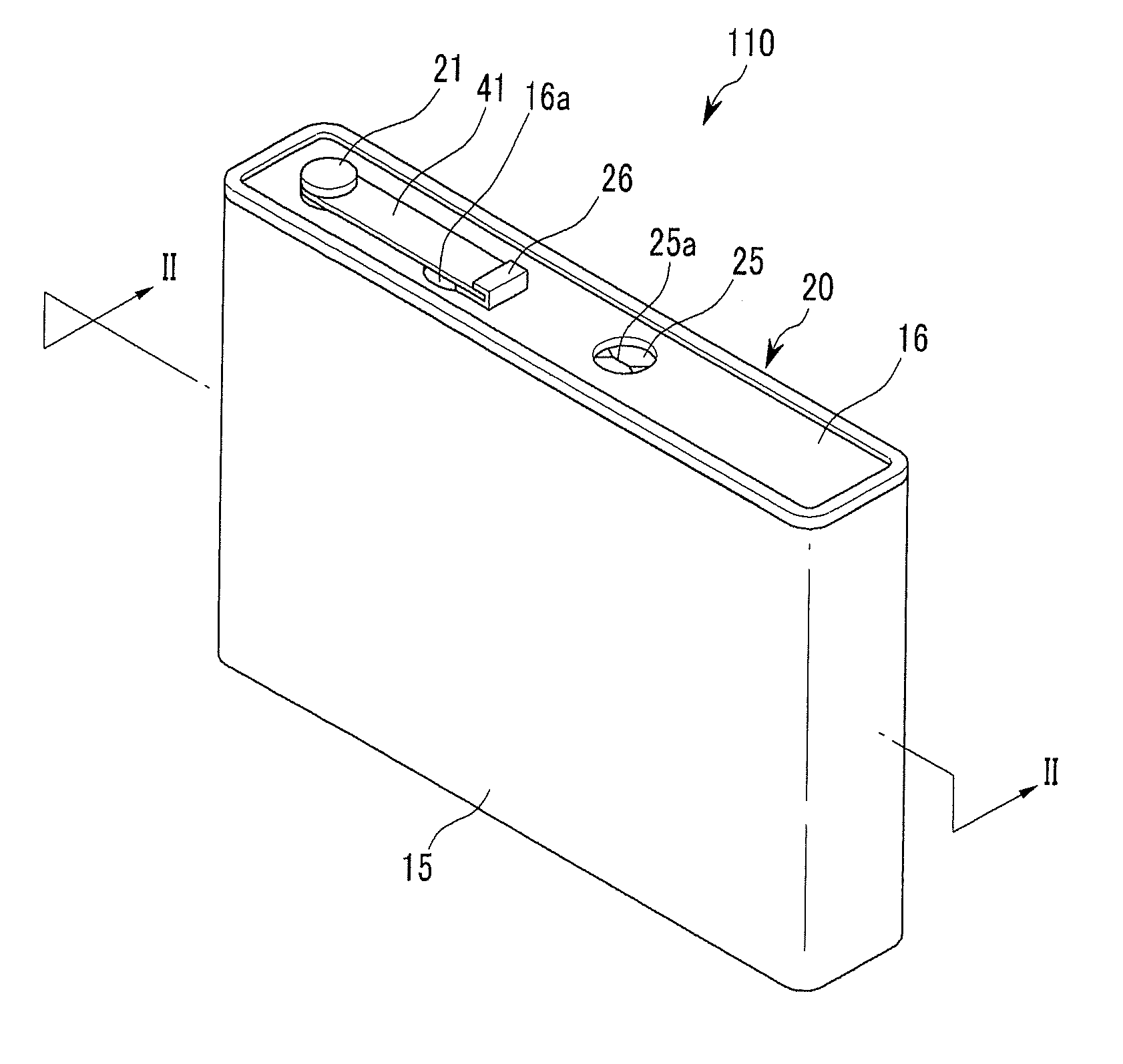
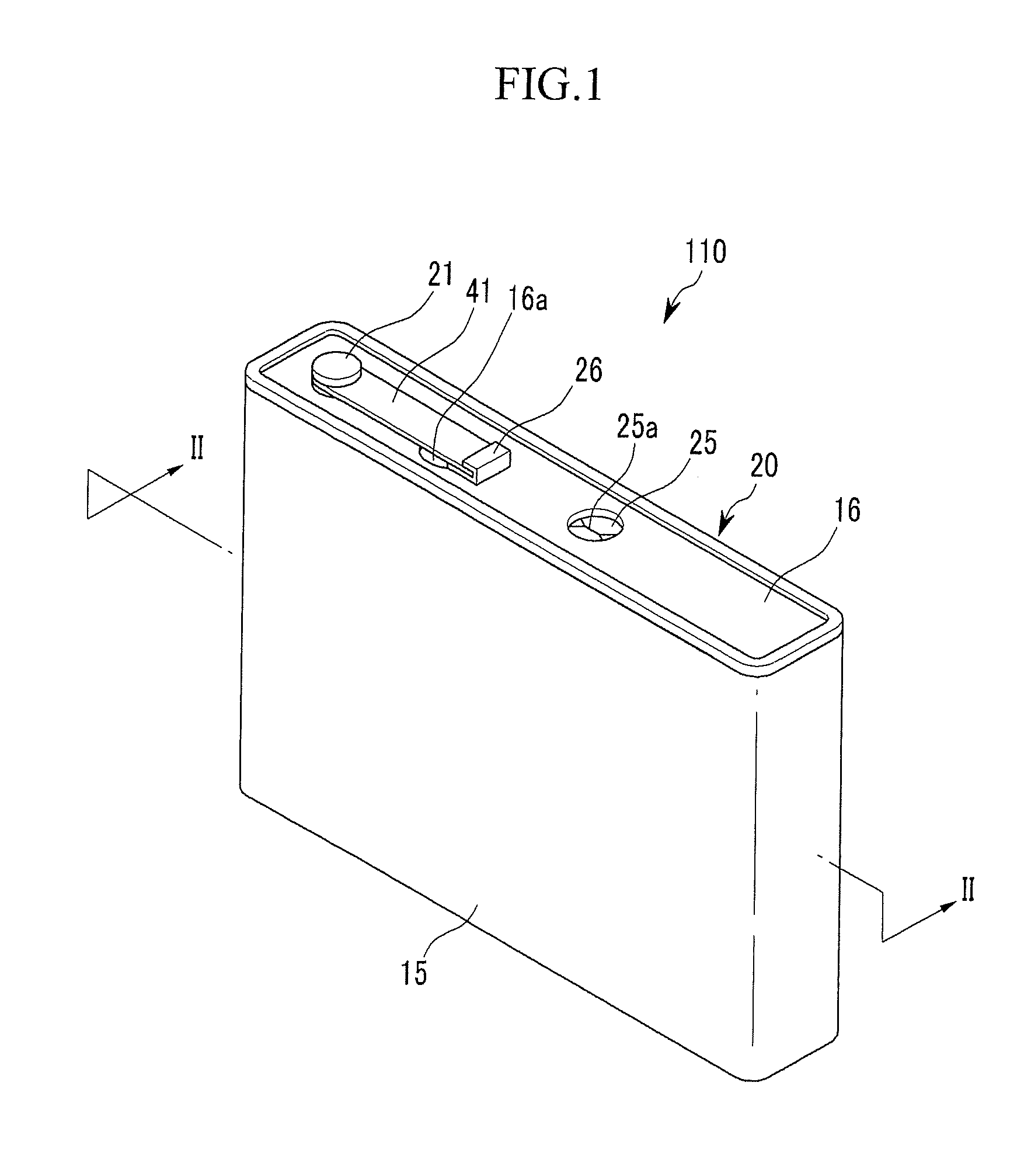
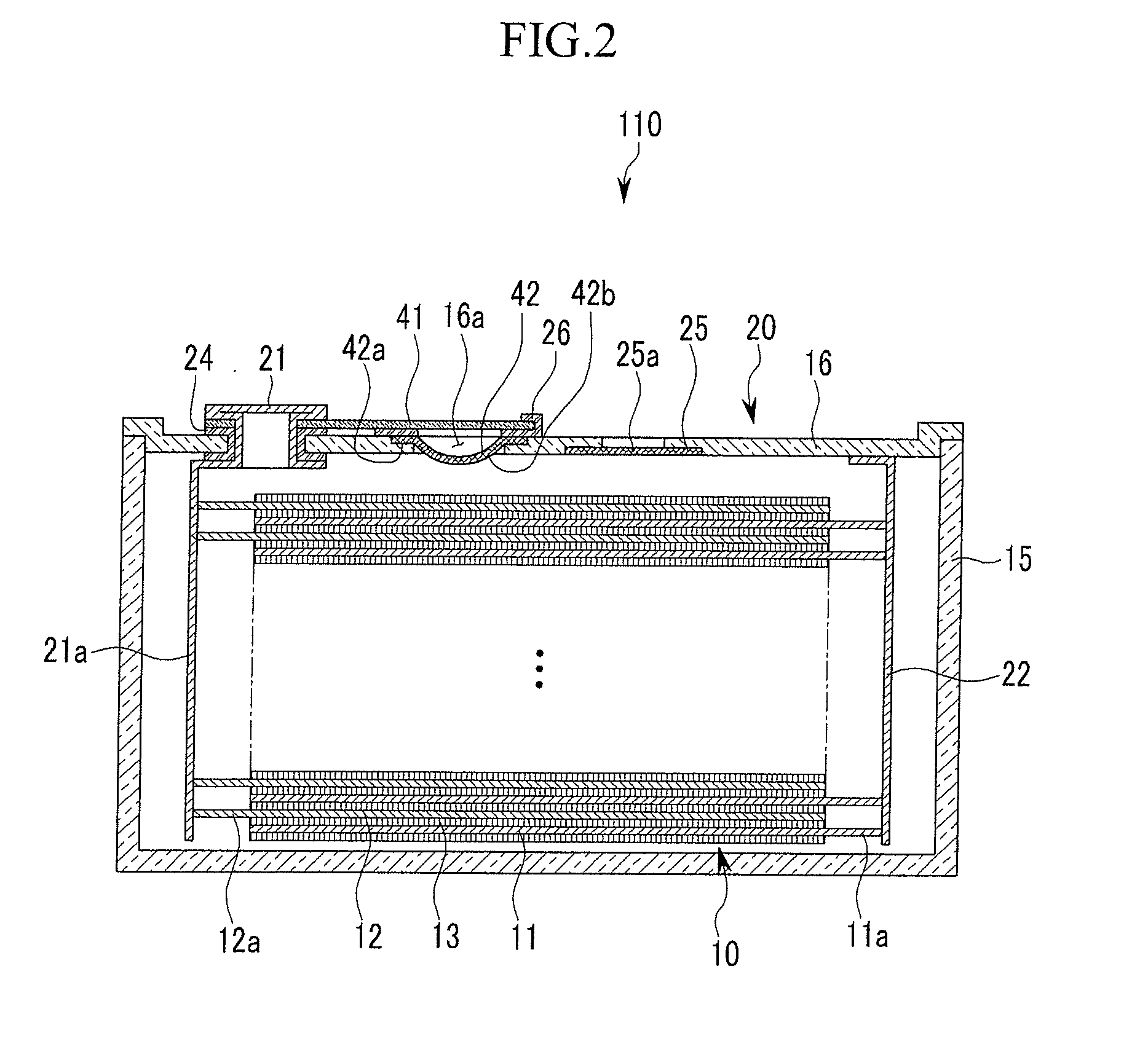
[0032]FIG. 1 is a perspective view showing a rechargeable battery in accordance with a first exemplary embodiment of the present invention, and FIG. 2 is a cross-sectional view taken along the line II-II of FIG. 1.

[...


PUM


Abstract

A rechargeable battery includes an electrode assembly, a case containing the electrode assembly and a cap assembly coupled to the case. The electrode assembly includes a first electrode, a second electrode, and a separator between the first electrode and the second electrode. The cap assembly includes a cap plate and a deformable plate attached to the cap plate and configured to deform in response to an increase in pressure inside the case to electrically couple the first electrode and the second electrode to each other.

Description

CROSS-REFERENCE TO RELATED APPLICATIONS[0001]This application claims priority to and the benefit of U.S. Provisional Application No. 61 / 224,392, filed Jul. 9, 2009, the entire content of which is incorporated herein by reference.BACKGROUND[0002]1. Field[0003]The described technology relates generally to a rechargeable battery.[0004]2. Description of the Related Art[0005]A rechargeable battery can be repeatedly charged and discharged, unlike a primary battery that is not intended to be recharged. A low capacity rechargeable battery is generally used for a small or portable electronic device, such as a mobile phone, a notebook computer, or a camcorder. A large capacity rechargeable battery is generally used as a power source for driving a motor for a hybrid electric vehicle.[0006]When excessive heat is generated in the rechargeable battery or when the internal pressure increases as an electrolyte solution in the rechargeable battery is decomposed, the battery may explode or catch fire...

Claims


Application Information

Patent Timeline
IPC IPC(8): H01M2/12H01M50/147H01M50/176H01M50/188H01M50/55H01M50/553H01M50/567H01M50/574H01M50/588H01M50/593
CPCH01M2/0217H01M2/0404H01M2/0473H01M2/0486H01M2/06H01M10/42H01M2/1241H01M2/30H01M2/34H01M2/345H01M2/08Y02E60/10H01M50/103H01M50/147H01M50/15H01M50/3425H01M50/578H01M50/588H01M50/593H01M50/567H01M50/55H01M50/553H01M50/574H01M50/176H01M50/188H01M50/531
Inventor KIM, YONG-SAMBYUN, SANG-WONKIM, HYO-SEOB
Owner ROBERT BOSCH GMBH
Why Eureka
Try Eureka