Gas burner

a burner and gas technology, applied in the field of gas burners, to achieve the effect of uniform distribution and dispersion

Inactive Publication Date: 2010-11-04
DESIGNGASPARTS
View PDF17 Cites 28 Cited by
  • Summary
  • Abstract
  • Description
  • Claims
  • Application Information

AI Technical Summary

Benefits of technology

[0012]In accordance with a further aspect of the invention, a cover may be installed on the top side of the burner cap and above the inner burner body. This cover may have a transparent or translucent insert that allows the visual observation of the flame on the inner burner body. This cover, when installed, will also more evenly distribute and disperse the heat from the inner burner when the inner burner is ope

Problems solved by technology

Prior such devices were fabricated usin

Method used


Image

  • Gas burner
  • Gas burner
  • Gas burner

Examples


Embodiment Construction

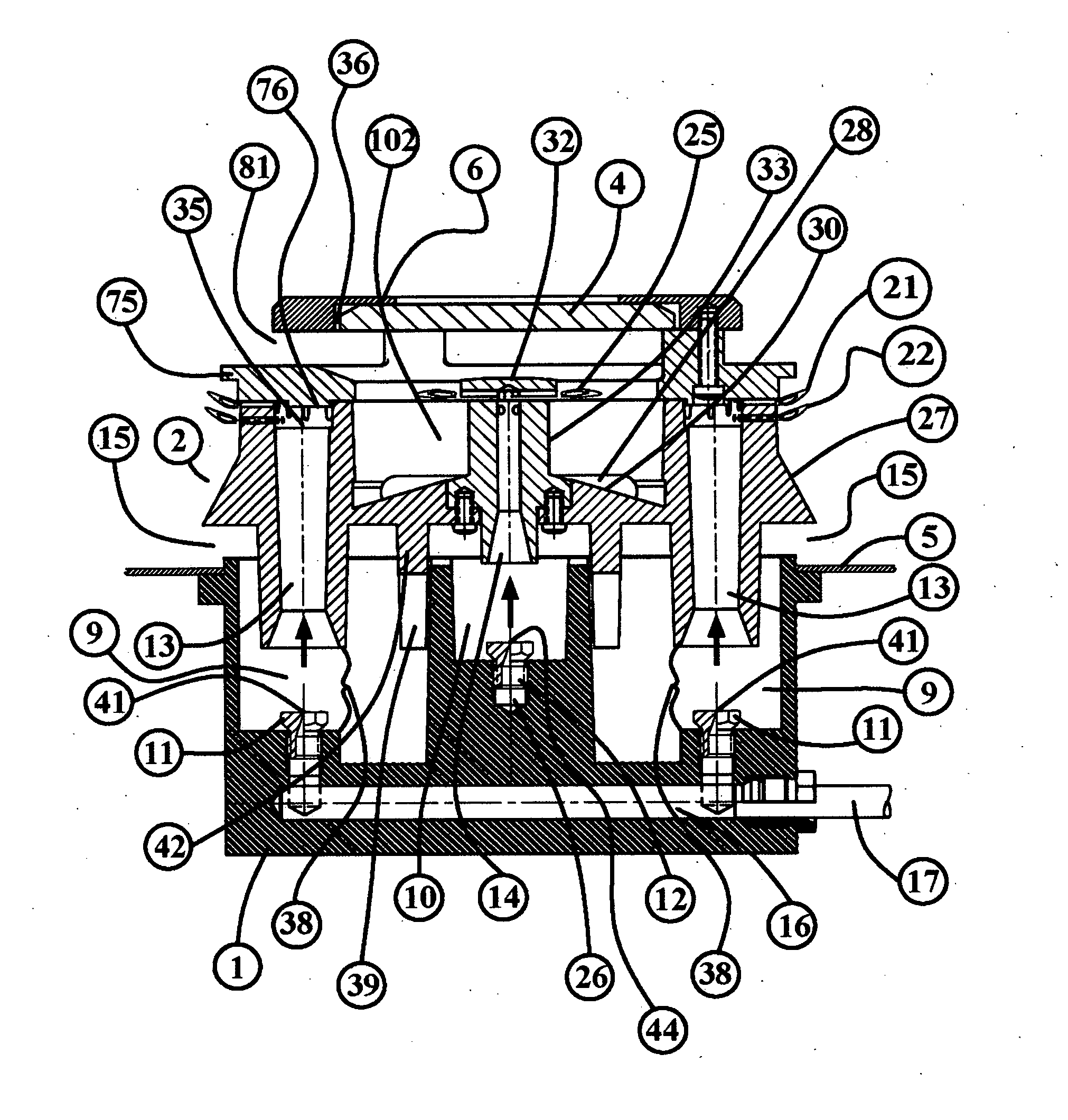
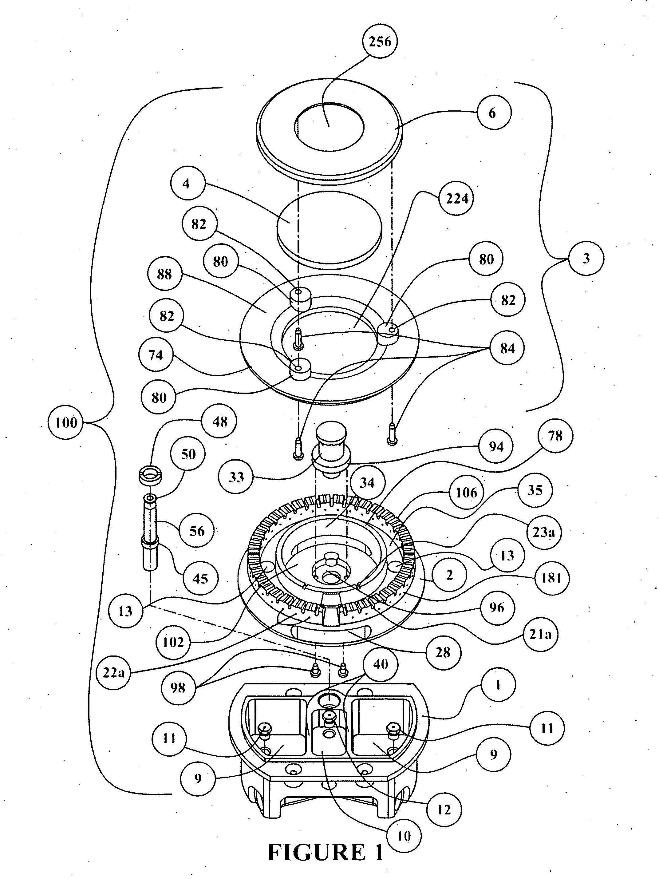
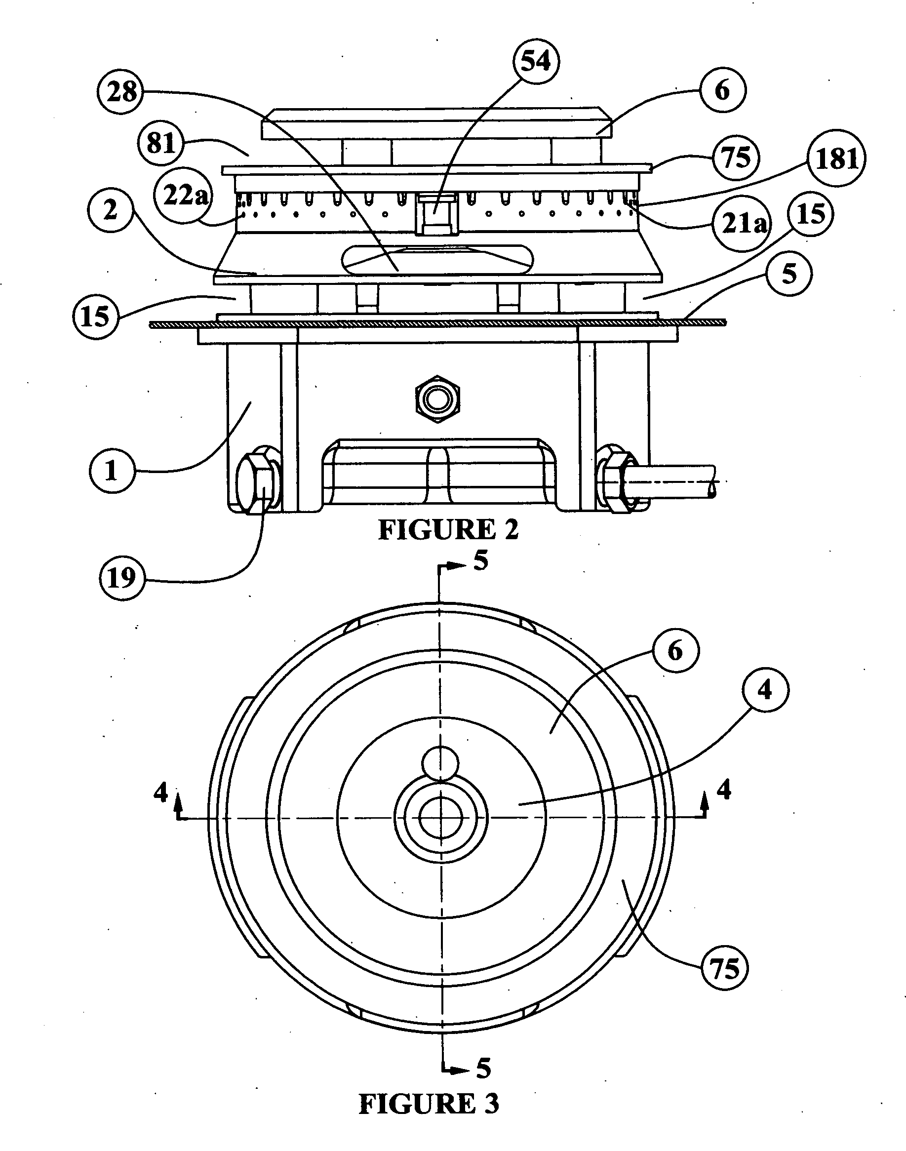
[0064]FIG. 1 shows an exploded view of the top flow gas burner assembly or burner assembly (100). With respect to FIG. 1, a gas burner assembly (100) is shown. The gas burner assembly (100) consists of a mixing cup (1), a burner body (2), a burner cap assembly (3), and a secondary burner (33), and an ignition electrode (56). FIG. 2 shows that the mixing cup (1) is generally attached either to a transverse member of an appliance or the base and / or the top (5) of the appliance. The burner body (2) is shown resting on the mixing cup (1). The burner body (2) is placed offsettedly from the mixing cup (1) creating an open air passage or primary air slot (15). The primary air slot (15) allows air into a primary air inlet chamber (9). FIG. 1 shows that there are at least two primary air inlet chambers (9) that feed a main burner chamber (35) that feed a first, and second flame ring or slot (21,22) as shown in FIG. 4.

[0065]A cover plate (6) is mounted on top of the burner cap assembly (3). T...


PUM


Abstract

What is shown is an improved gas burner assembly that is easily adapted to attach to a range top or cooktop, or the floor of the range and can draw air from either above the range top level by external vents or from below range top level through an open style mixing cup. The improved gas burner assembly uses a plurality of flame rings providing the user a wide variety of temperature settings starting from a low intensity simmer to high intensity cooking heat. A gas transfer channel provides a sustaining ignition source. The gas transfer channel has sustaining flame buttons interior to the burner body, and provides the initial ignition for the main flame rings. The gas transfer channel additionally has slots that provide additional sustaining flames for the main flame rings located on the exterior of the burner body. The improved gas burner assembly additionally uses a cover plate of transparent or translucent, heat proof material that allows the user to observe the interior of the burner to which flame rings have ignited. The cover plate also transfers heat from the internal flame rings to the cooking utensil imparting a more uniform transfer of heat to the cooking utensil.

Description

BACKGROUND OF THE INVENTIONField of the Invention[0001]The present invention relates to the field of gas burners that are used in the home. Specifically, these burners are used on surface units in household gas cooking appliances.SUMMARY OF THE INVENTION[0002]Atmospheric gas burners commonly used as surface units in household gas cooking appliances generally come in different sizes. The actual physical size of the burner as well as its energy output, which is referred to as BTU's, (British thermal units) are two of many design elements that are used to size the gas burners. The various burner sizes are needed to cook the myriad number of food items that are cooked in different sizes and shapes of cooking containers to satisfy the countless taste requirements of the population.[0003]Gas burners have typically a maximum energy output, which is specified in BTU's, and a minimum energy output, also specified in BTU's. To regulate this energy output the gas flow to each burner is control...

Claims


Application Information

Patent Timeline
IPC IPC(8): F23Q7/22F23Q7/06F23D14/62
CPCF23D14/06F23D14/64F23L9/00F23D2900/14063F23L1/00F23D2900/14062F23D2900/14064
Inventor HARNEIT, UWE
Owner DESIGNGASPARTS
Why Eureka
Try Eureka