Illuminating device and display device

a technology which is applied in the field of illumination device and display device, can solve problems such as difficulty in improving contrast ratio, and achieve the effects of reducing light reflecting, improving contrast ratio, and intensifying the luminance peak

Inactive Publication Date: 2010-11-11
SHARP KK
View PDF11 Cites 21 Cited by
  • Summary
  • Abstract
  • Description
  • Claims
  • Application Information

AI Technical Summary

Benefits of technology

[0014]The aforementioned structure of the present invention is provided with a transparent EL sheet which is disposed at the back surface side of the display panel and kept transparent in a non-luminous state, and a reflection sheet which reflects the light from the light source to the display panel. When at least a part of the surface of the transparent. EL sheet is brought into the luminous state corresponding to the image display on the display panel, the resultant emitted light is irradiated to the display panel together with the light from the light source and the light reflecting from the reflection sheet. If there is a bright display portion for the image display on the display panel, the surface corresponding to the bright display portion on the transparent EL sheet disposed at the back surface side of the display panel is brought into the luminous state, and the rest of the surface is not allowed to be luminous. This makes it possible to emphasize the white portion of the bright display on the display panel. The peak luminance may be intensified at the brightest part (white) while keeping the darkest part (black) of the image displayed on the display panel dark, resulting in an improved contrast ratio.
[0015]The reflection sheet which is capable of changing reflectance of at least a part of its surface corresponding to the image displayed on the display panel may be used as the one for reflecting the light from the light source to the display panel. In such a case, if there is a dark display portion for the image display on the display panel, the reflectance of the surface corresponding to the dark display portion on the reflection sheet is changed so as to reduce the light reflecting on such surface. This makes it possible to further darken the black portion of the dark display of the image on the display panel, resulting in a further improved contrast ratio.

Problems solved by technology

If the peak luminance at the brightest part (white) on the screen of the liquid crystal display panel 101 is intensified, the black portion at the darkest part (black) cannot appear sufficiently darkened, resulting in difficulty in improvement of the contrast ratio.

Method used


Image

  • Illuminating device and display device
  • Illuminating device and display device
  • Illuminating device and display device

Examples


Embodiment Construction

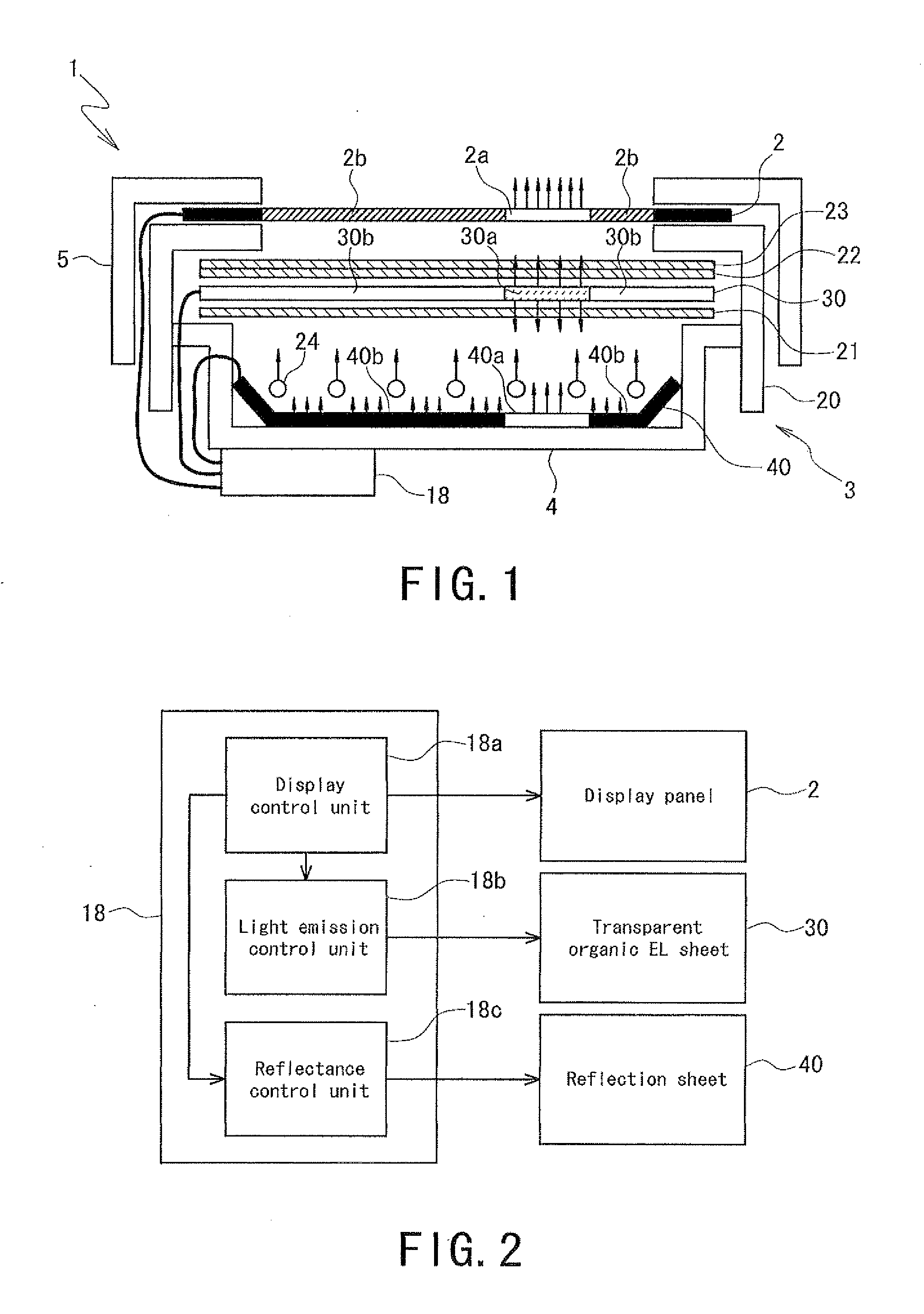
[0025]Preferred embodiments according to the present invention will be described in detail referring to the drawings. FIG. 1 schematically illustrates a structure of a liquid crystal display device according to a preferred embodiment of the present invention.

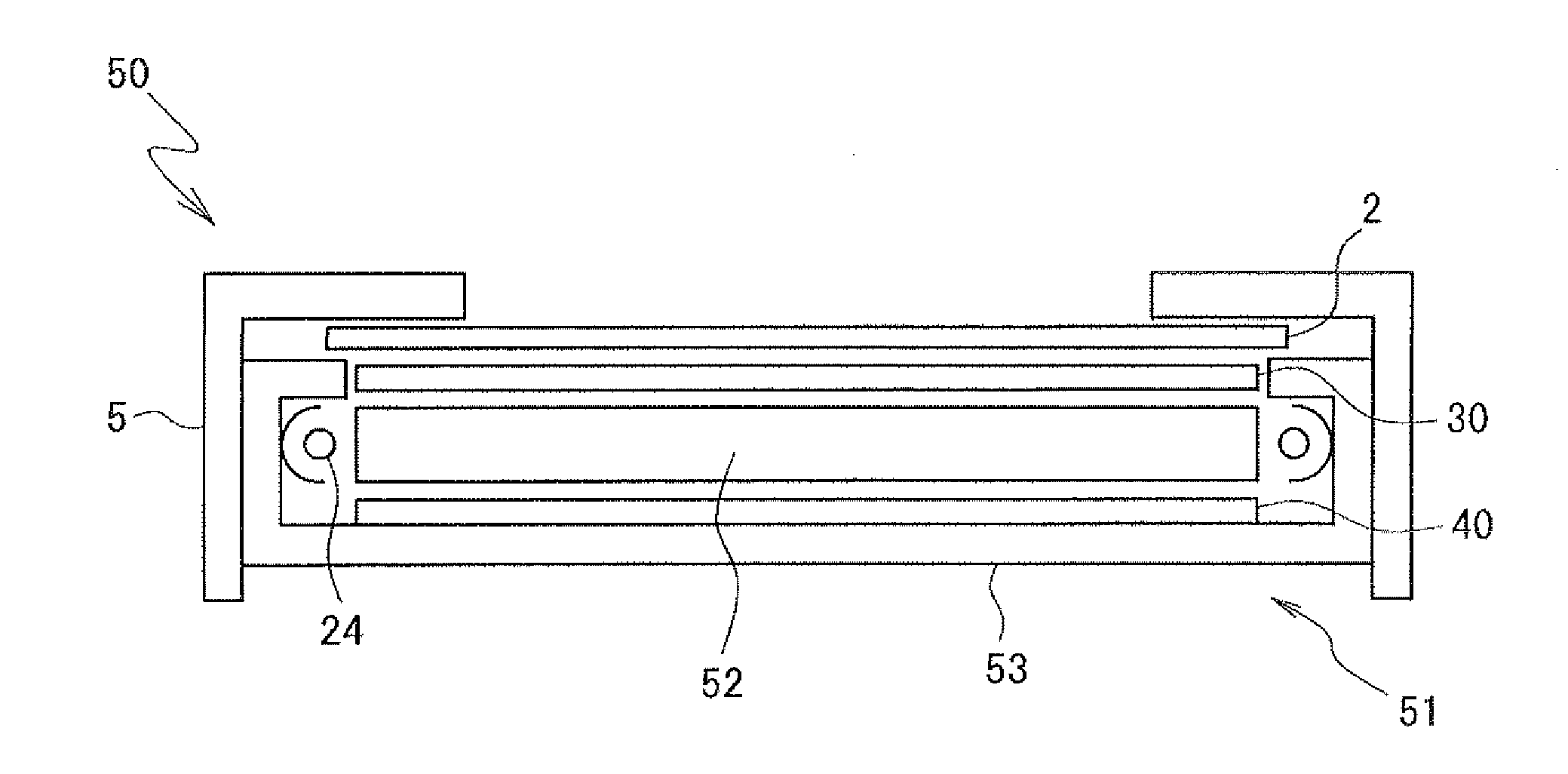
[0026]A liquid crystal display device 1 illustrated in the drawing includes a liquid crystal display panel 2 and an illuminating device 3. The liquid crystal display panel 2 is formed by laminating two substrates having liquid crystal sealed therebetween, and fixed to a chassis 4 of the illuminating device 3 with bezels 5.

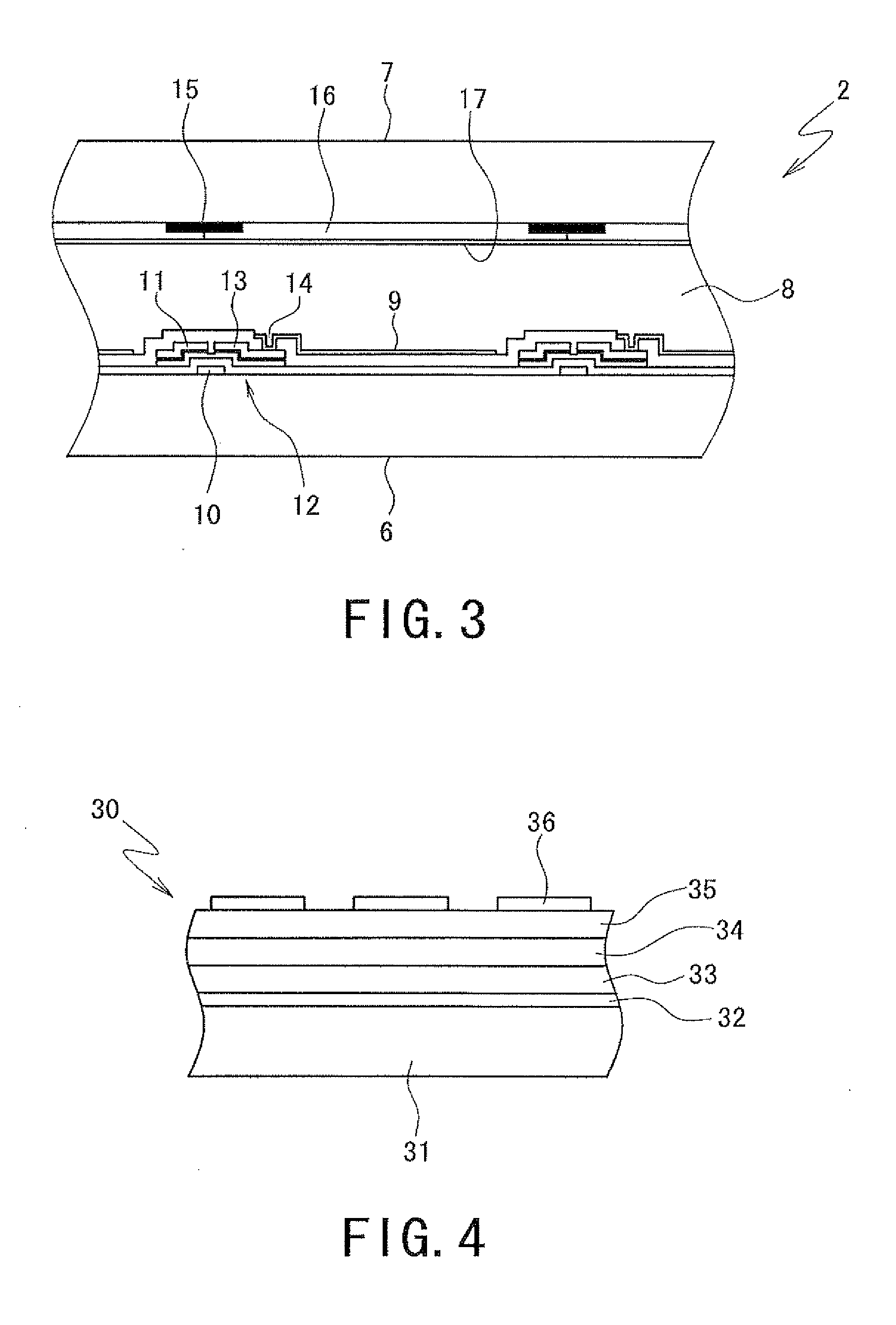
[0027]Referring to FIG. 3, a liquid crystal 8 is sealed between a thin film transistor (TFT) substrate 6 and a color filter (CF) substrate 7 which are oppositely arranged to form the liquid crystal display panel 2. The TFT substrate 6 is provided with plural pixel electrodes 9 arranged in matrix. A gate electrode 10 and a source electrode 11 are formed to be orthogonal to each other around the respective pixel ...


PUM

PropertyMeasurementUnit
transparentaaaaaaaaaa
reflectanceaaaaaaaaaa
heightaaaaaaaaaa

Abstract

A display device for performing image display by irradiating light from a light source to a display panel includes a transparent EL sheet which is disposed at aback surface side of the display panel and kept transparent in a non-luminous state, a reflection sheet which reflects the light from the light source to the display panel, a display control unit which controls the image display on the display panel, and a light emission control unit which controls light emission on the transparent EL sheet, wherein when the light emission control unit brings at least a part of a surface of the transparent EL sheet into a luminous state corresponding to the image display on the display panel controlled by the display control unit, an emitted light is irradiated to the display panel together with the light from the light source and the light reflecting from the reflection sheet.

Description

BACKGROUND OF THE INVENTION[0001]1. Field of the Invention[0002]The present invention relates to a display device provided with an illuminating device for irradiating light to a light transmission type display panel, and more particularly, to a display device for an image display with improved contrast.[0003]2. Description of the Related Art[0004]Generally, a flat type display device, such as a liquid crystal display device provided with a light transmission type liquid crystal display panel for example, has an illuminating device disposed at a back surface side of the liquid crystal display panel. The illuminating device includes a cold cathode fluorescent lamp (hereinafter referred to as CCFL) as a light source for irradiating the light with adjusted property to the back surface side of the liquid crystal display panel. The irradiated light transmits the liquid crystal display panel so as to visualize the image displayed on the front of the liquid crystal display panel.[0005]FIG. ...

Claims


Application Information

Patent Timeline
Patent Type & Authority Applications(United States)
IPC IPC(8): G09G3/36G09G3/34F21V7/22G02F1/1335
CPCG02F1/133602G02F1/133605G02F2001/133614G09G2320/066G09G3/3426G09G3/36G09G2300/023G02F2203/62G02F1/133614
Inventor OKA, HIDEKAZUMORIMOTO, TAKASHI
Owner SHARP KK
Why Eureka
Try Eureka