Light Fixture with Directed LED Light

a technology of led light and light fixture, applied in the field of light fixture, can solve the problems of loss of light or large areas of high illumination, difficult to achieve uniformity, and difficult to define uniformity and achieve i

Inactive Publication Date: 2010-11-11
LIGHTOLOGY
View PDF7 Cites 82 Cited by
  • Summary
  • Abstract
  • Description
  • Claims
  • Application Information

AI Technical Summary

Benefits of technology

[0021]In one aspect of the present invention, a light fixture for lighting a wall is provided, including a supporting base and at least one light emitting diode (LED) on the base emitting light in a cone having a central axis. A first reflector is curved between a first lip secured to the base adjacent the LED and a second lip spaced from the base, with the central axis of the cone intersecting the first reflector between the first and second...

Problems solved by technology

For example, effective wall grazing fixtures will distribute light along the height of the wall, with uniformity of illumination desired between the lowest and highest vertical areas of the wall, which uniformity is hard to define and difficult to achieve.
However, with the 360 degree output of fluorescent fixtures, it is difficult to distribute the light efficiently through the aperture.
This results in lost light or large areas of high illumination and large areas of poor light, undesirably creating an uneven lighting wherein only half of the wall is only lit well.
While theoretically putting LEDs close together could help in causing scalloping from ...

Method used


Image

  • Light Fixture with Directed LED Light
  • Light Fixture with Directed LED Light
  • Light Fixture with Directed LED Light

Examples


Embodiment Construction

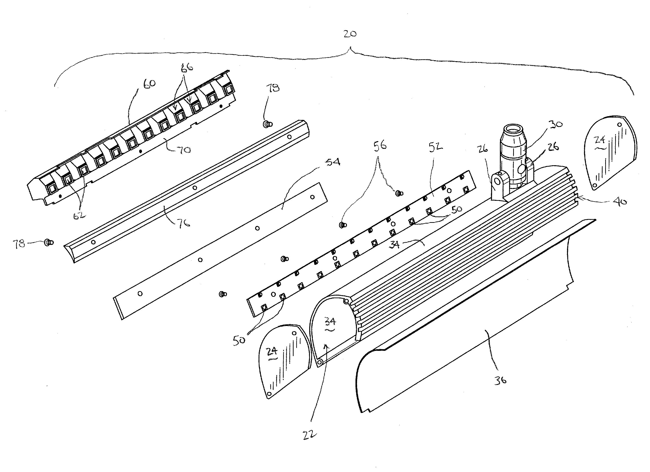
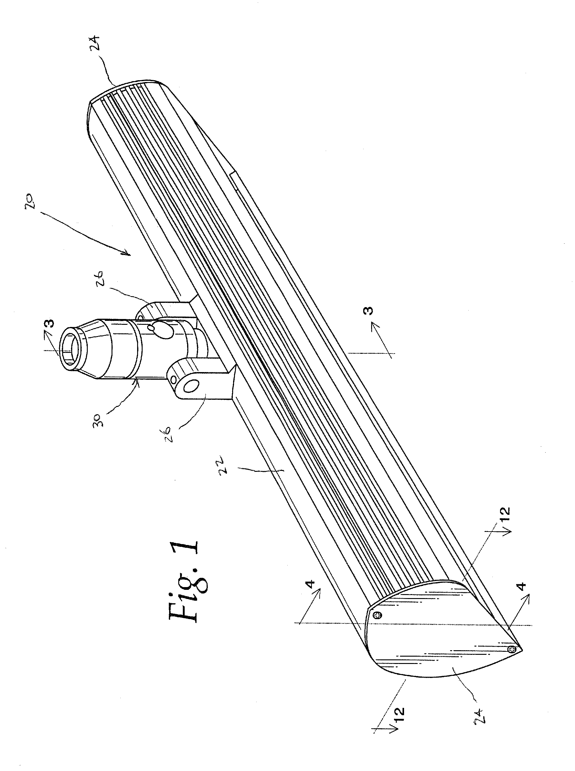
[0063]FIGS. 1-4 illustrate one light fixture 20 which incorporates at least some features of the present invention. As seen in FIG. 1, the fixture 20 includes a base or housing 22 with side plates or covers 24. Brackets 26 on the housing 22 are suitably secured to a support 30, whereby the entire fixture 20 may be supported by securement of the support 30 to a ceiling, for example. As further described below, the support 30 may allow for remote adjustment of the position (orientation) of the fixture 20 to provide the desired lighting from the fixture 20.

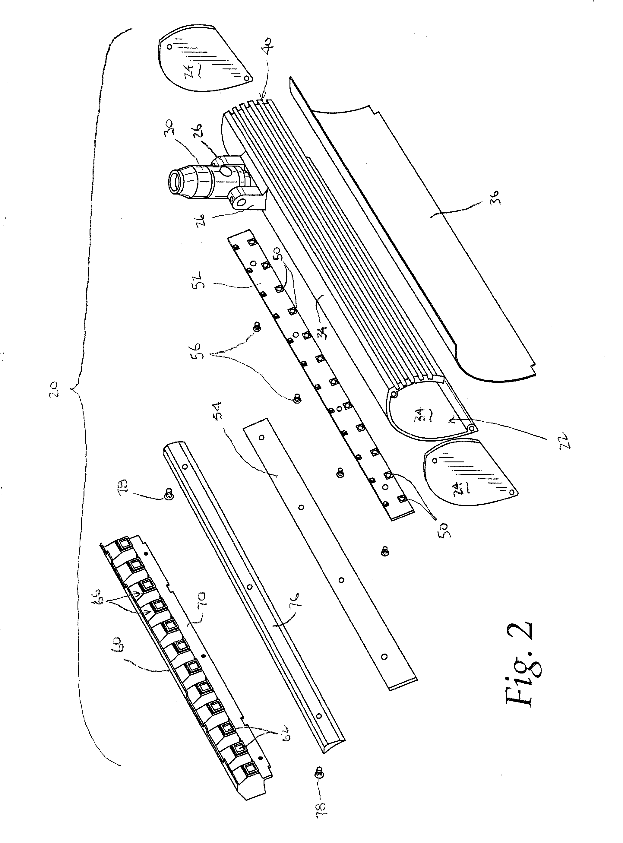
[0064]FIG. 2 further illustrates, in an exploded view, the major components of and in the housing 22.

[0065]Specifically, the housing 22 itself extends linearly to form a semi-tubular shape with an opening along its length through which light is emitted.

[0066]A first, generally parabolic, portion 34 of the housing 22 encloses a first reflector 36 which also extends linearly and has a generally parabolic shape. The first reflector 36 i...


PUM

PropertyMeasurementUnit
Angleaaaaaaaaaa
Angleaaaaaaaaaa
Angleaaaaaaaaaa

Abstract

A light fixture for lighting a wall, including a supporting base and at least one light emitting diode (LED) on the base emitting light in a cone having a central axis. A first reflector is curved between a first lip secured to the base adjacent the LED and a second lip spaced from the base, with the central axis of the cone intersecting the first reflector between the first and second lips. A second reflector defines a reflecting enclosure for and includes first and second generally flat surfaces on opposite sides of the LED and substantially symmetrical about a plane which includes the light cone central axis, and a third generally flat surface intersecting both of the first and second surfaces, whereby the first reflector is oriented to reflect light from both the LED and the second reflector in a beam having a selected shape.

Description

CROSS REFERENCE TO RELATED APPLICATION(S)[0001]Not applicable.STATEMENT REGARDING FEDERALLY SPONSORED RESEARCH OR DEVELOPMENT[0002]Not applicable.REFERENCE TO A MICROFICHE APPENDIX[0003]Not applicable.TECHNICAL FIELD[0004]The present invention is directed toward light fixtures, and particularly toward light fixtures which direct light from light emitting diodes (LEDs).BACKGROUND OF THE INVENTION AND TECHNICAL PROBLEMS POSED BY THE PRIOR ART[0005]Light fixtures are, of course, used for a variety of purposes. Beyond simply providing light to enable people to see better, fixtures are also sometimes used for architectural and design purposes, for example to highlight features to provide a desired aesthetic appearance.[0006]For example, in some structures it is desirable to create a large visual hot spot or high point of illumination to draw attention to that area. Accent lighting is used for such purposes.[0007]Wall grazing fixtures, by contrast, are used for different architectural and...

Claims


Application Information

Patent Timeline
IPC IPC(8): F21V1/00
CPCF21S8/026F21S8/043F21V7/0008F21V7/0025F21V7/005F21Y2101/02F21V7/22F21V15/015F21V17/16F21V21/15F21V21/30F21V7/06F21V29/507F21Y2103/10F21Y2115/10F21V7/24F21V7/28
Inventor O'BRIEN, AARONPETRYUCHENKO, OLEG
Owner LIGHTOLOGY
Why Eureka
Try Eureka