Electrolytic cell

Inactive Publication Date: 2010-11-11
KAO SUENG NIEN
View PDF1 Cites 2 Cited by
  • Summary
  • Abstract
  • Description
  • Claims
  • Application Information

AI Technical Summary

Benefits of technology

[0007]The main objective of the present invention is to provide an electrolytic cell that is recyclable, has no depolarizer and a low environmental impact.

Problems solved by technology

However, the depolarizer may be consumed so decreasing battery efficiency during use.
Therefore, concentration of depolarizer should be frequently and regularly monitored and added to the electrolyte, thereby raising maintenance and running costs.

Method used


Image

  • Electrolytic cell
  • Electrolytic cell
  • Electrolytic cell

Examples


first embodiment

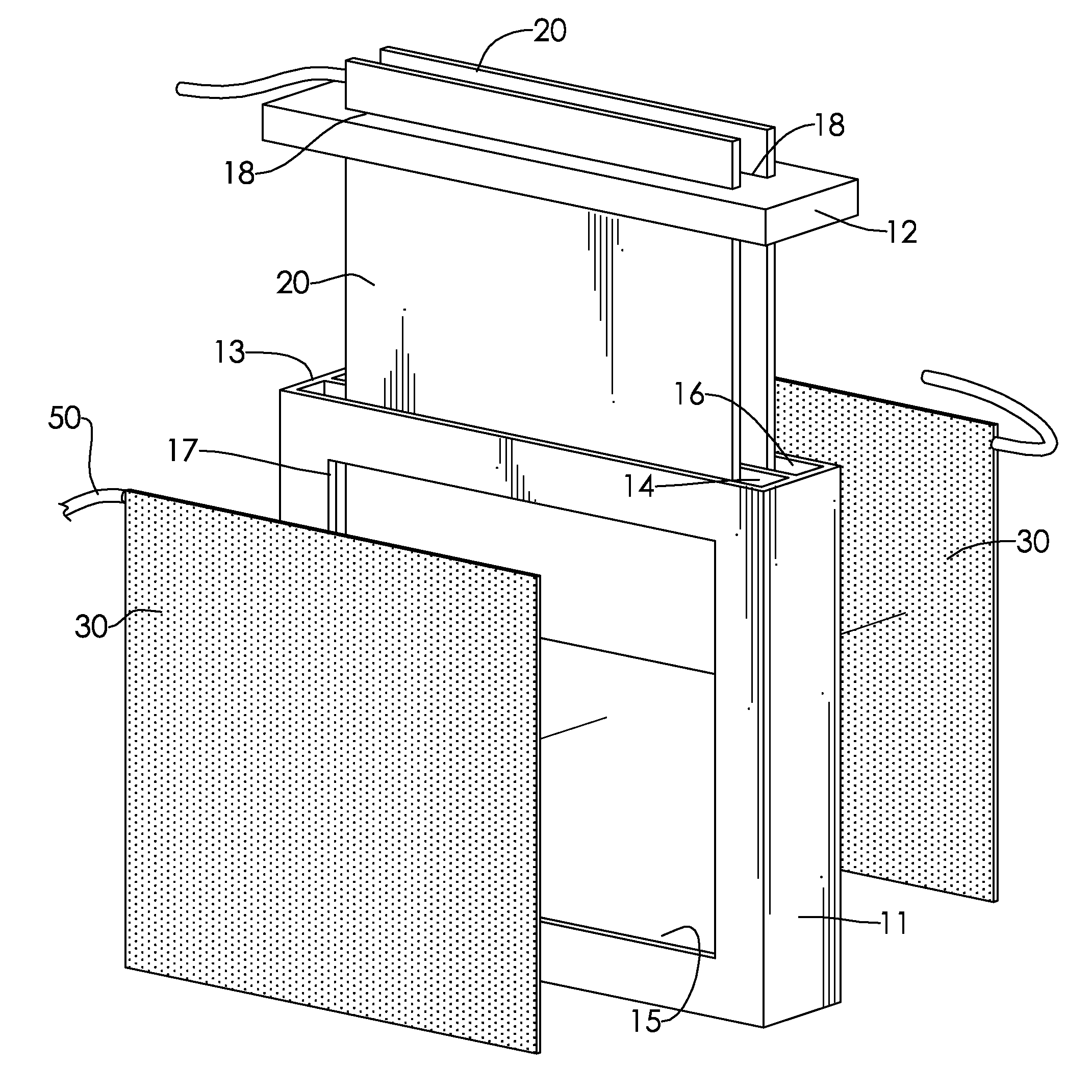
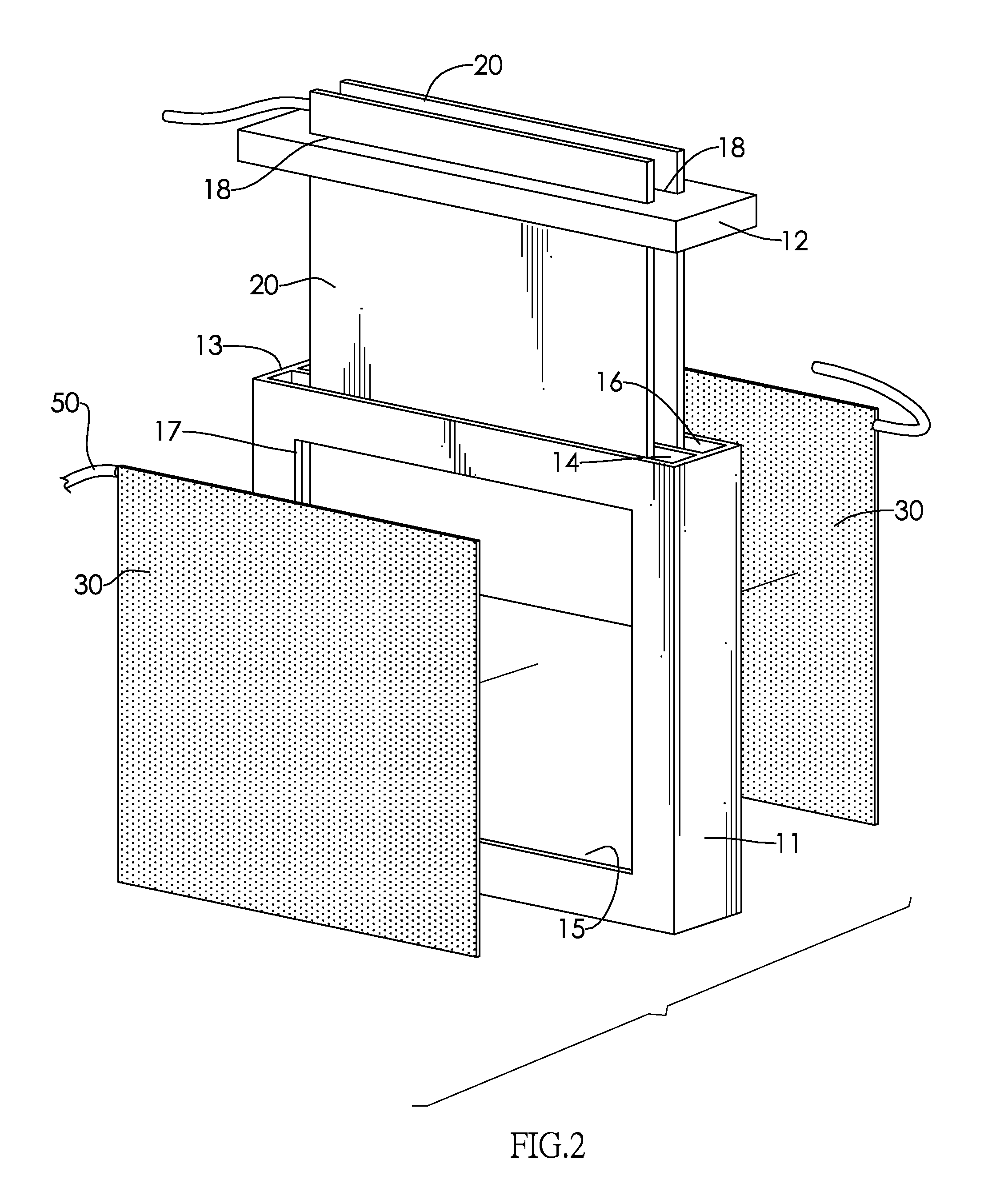
[0020]In the first embodiment, two through holes (17) and two inserting hole (18) may be implemented. The through holes (17) are respectively formed through the sidewalls. The base (11) may further have a partition (14). The partition (14) is formed on the inner surface of the chamber and divides the at least one chamber into a first chamber (15) and a second chamber (16). The first chamber (15) is adjacent to and communicates with through hole (17). The second chamber (16) is adjacent to and communicates with the other through hole (17).

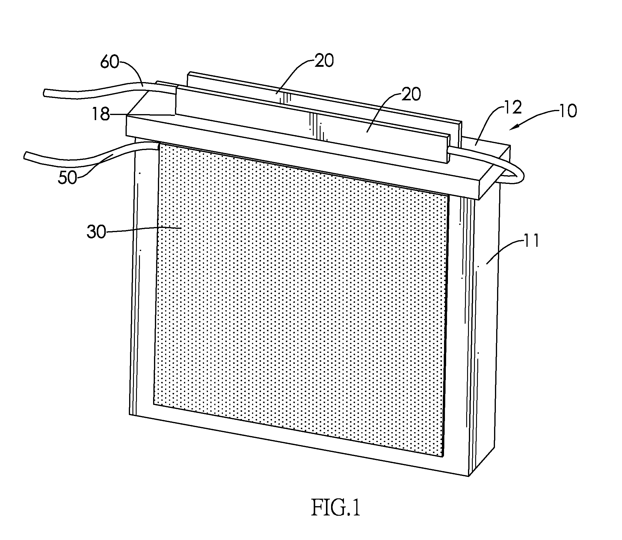
[0021]The at least one metal plate (20) is at least one anode, corresponds to and is respectively mounted through the at least one inserting hole (18) of the cover (12) of the insulating body (10). In the first embodiment, two metal plate (20) may be implemented and are respectively mounted in two inserting holes (18) of the cover (12) of the insulating body (10) and may be magnesium.

[0022]With further reference to FIG. 5, the at least one carbon pl...

second embodiment

[0028]With reference to FIG. 6, the electrolytic cell of a second embodiment further has two protecting covers (70). Two protecting covers (70) are respectively mounted on two sidewalls of the insulating body and each protecting cover (70) has multiple slots (71) to allow the air pass to the protecting covers (70).

[0029]When the electrolytic cell is used, the first chamber (15) and second chamber (16) are filled with water serving as an electrolyte so that the anode (20) in the first chamber (15) and the carbon plate (30) outside the first chamber (15) are connected to form a first electrolyte cell to supply power. The anode (20) in the second chamber (16) and the carbon plate (30) outside the second chamber (16) are connected to form a second electrolyte cell to supply power. The first and second electrolyte cells are connected together in series by the wire. Due to the carbon plate (30) contacts the air and the water and allows the air pass through the depolarization plates (32), ...


PUM


Abstract

An electrolytic cell has an insulating body, at least one metal plate, at least one carbon plate, an anode terminal connected electrically to one of at least one carbon plate and a cathode terminal connected electrically to one of at least one metal plate. The insulating body has a base and a cover. The base has two sidewalls, an opening, at least one chamber and at least one through hole. The at least one chamber is formed in the base. The at least one through hole is formed through one or all of the sidewalls. The at least one metal plate is mounted in the cover. The at least one carbon plate respectively covers the at least one through hole. Due to the carbon plate allows the air go through the carbon plate, the air can be as a depolarizer.

Description

BACKGROUND OF THE INVENTION[0001]1. Field of the Invention[0002]The present invention relates to a power supply, especially to a recyclable electrolytic cell without a depolarizer.[0003]2. Description of the Prior Arts[0004]Battery materials are being actively researched for improved environmental impact.[0005]A battery may be an electrolytic cell having two electrodes, an electrolyte and a depolarizer. The depolarizer is added to the electrolyte to prevent a surface of the electrode material undergoing chemical reactions for improved battery efficiency. However, the depolarizer may be consumed so decreasing battery efficiency during use. Therefore, concentration of depolarizer should be frequently and regularly monitored and added to the electrolyte, thereby raising maintenance and running costs.[0006]To overcome the shortcomings, the present invention provides an electrolytic cell to mitigate or obviate the aforementioned problems.SUMMARY OF THE INVENTION[0007]The main objective o...

Claims


Application Information

Patent Timeline
IPC IPC(8): H01M2/02
CPCH01M12/065H01M6/04
Inventor KAO, SUENG-NIEN
Owner KAO SUENG NIEN
Why Eureka
Try Eureka