

Elevator speed measuring device and elevator
A speed measurement, elevator technology, applied in transportation and packaging, elevators, etc., can solve problems such as image impact, and achieve the effect of reducing environmental impact
- Summary
- Abstract
- Description
- Claims
- Application Information
AI Technical Summary
Problems solved by technology
Method used
Image

Examples
no. 1 approach
[0054] Here, an embodiment in which the speed of an elevator car is measured from a dark-field image of a rope will be described.
[0055] First, the structure of the elevator 1 of this embodiment is demonstrated.
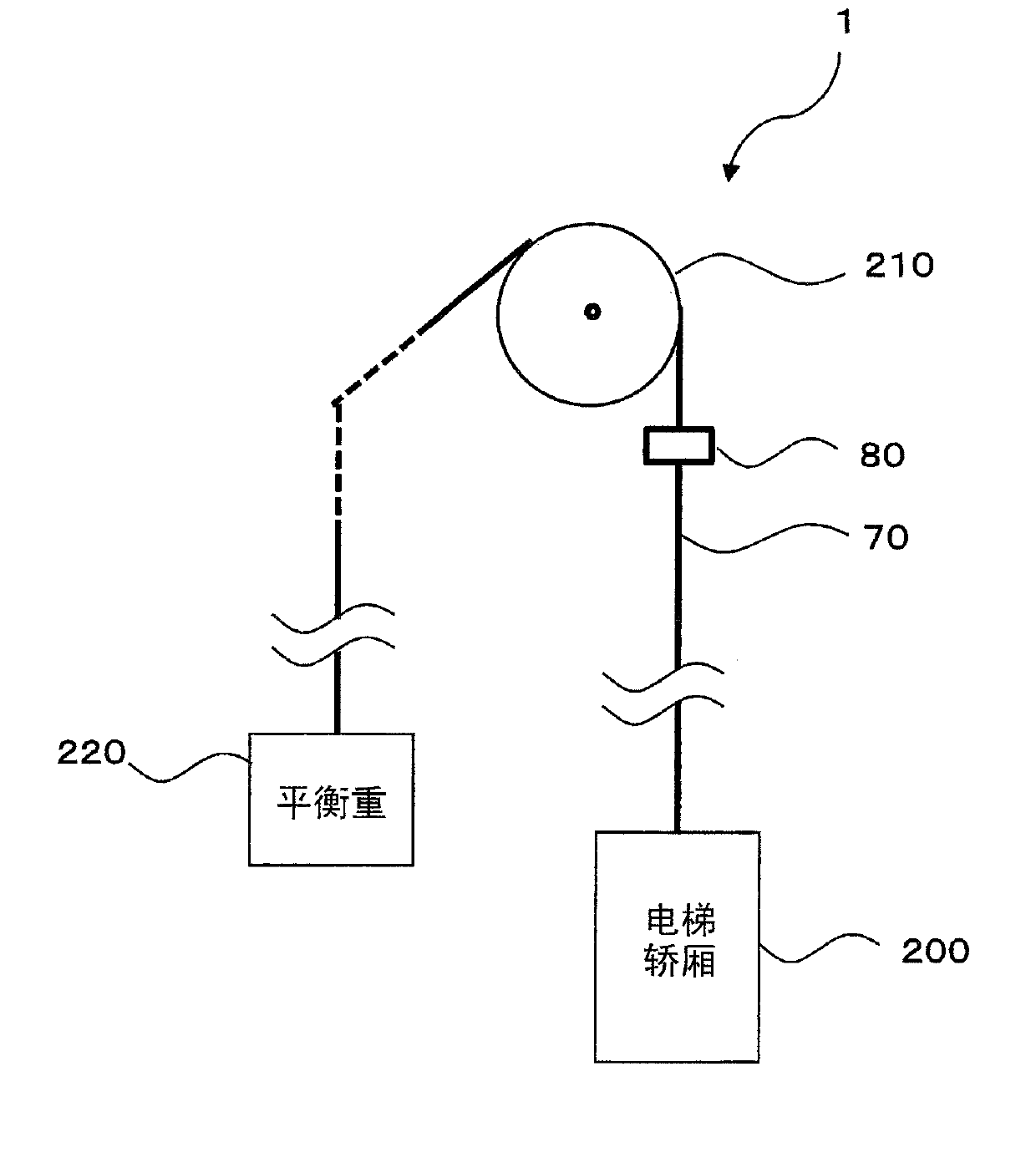
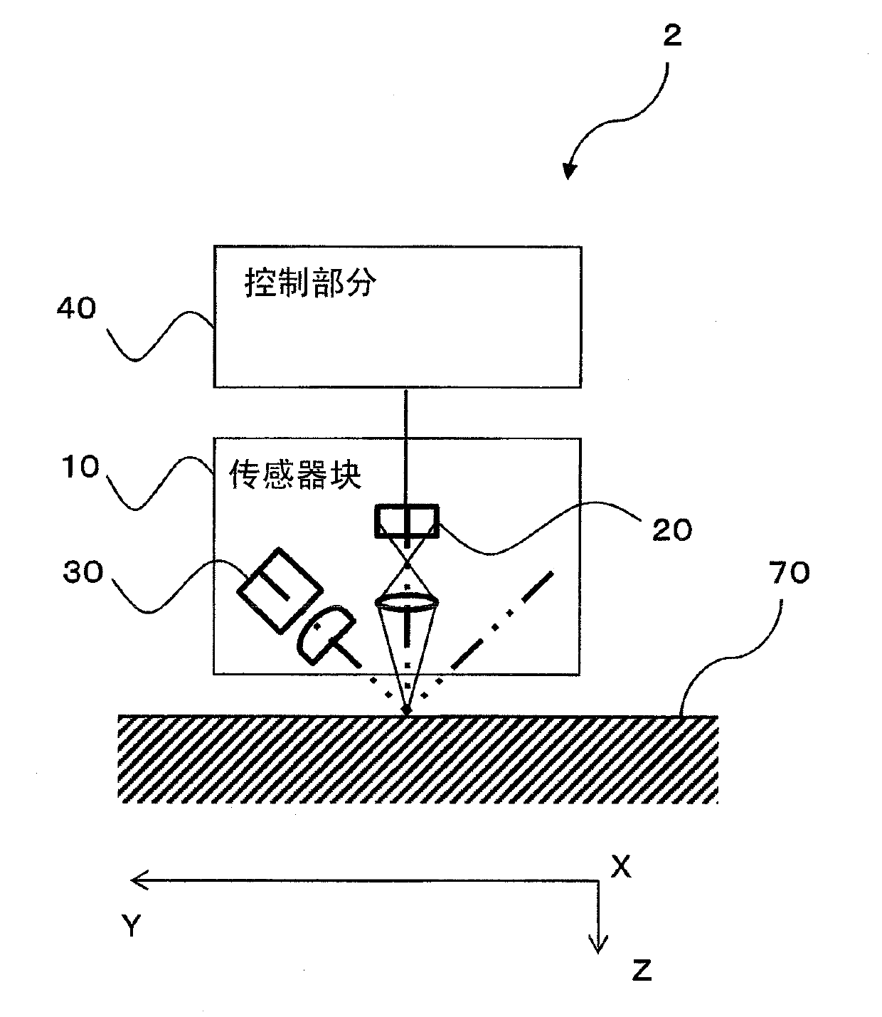
[0056] figure 1 It is a schematic diagram which shows the structure of the elevator 1 which concerns on 1st Embodiment. The elevator 1 of this embodiment has: a pulley 210, which is arranged at the uppermost part of the hoistway, and rotates under the drive of a driving part not shown in the figure; a sling 70, which is wound in a groove around the pulley 210; a car 200 connected to one end of the sling 70 for transporting people and cargo, etc.; In addition, the elevator 1 further has a monitoring section 2 fixed in the vicinity of the pulley 210 in the hoistway for monitoring the state of the rope 70 . The sling 70 supports the elevator car 200 and moves with the movement of the elevator car 200 . The monitoring part 2 is fixed in the lifting passage. The mo...
no. 2 approach
[0064] In this embodiment, the embodiment of the wire breakage detection will be further described in addition to the speed measurement processing.
[0065] The structure of the elevator 1 of this embodiment is the same as that of 1st Embodiment.
[0066] Next, the wire breakage detection processing will be described.
[0067] Figure 4 is a flowchart showing wire breakage detection processing. The control section 40 performs the wire breakage detection processing after at least two speed measurement processings. First, the control part 40 reads a plurality of car speeds stored in the memory (S100) to calculate a change in car speed, that is, acceleration (S110). Next, the control part 40 judges whether sudden acceleration has occurred based on the calculated acceleration (S120). That is, the control section 40 judges whether the calculated acceleration exceeds a preset rated acceleration.
[0068] When it is judged that the sudden acceleration has not occurred (No in S12...
no. 3 approach
[0073] An embodiment in which the entire circumference of the sling 70 is set as the target area will be described below.
[0074] The elevator 1 of this embodiment has the monitoring part 3 instead of the monitoring part 2. Figure 5 is a schematic diagram showing the configuration of the monitoring section 3 of the third embodiment, Figure 6 It is a perspective view which shows the structure of the whole circumference|surroundings imaging part 80. The monitoring section 3 has an all-around photographing section 80 enclosing the target area of the sling 70 for capturing an image of the target area, and a control section 90 . The control section 90 performs control of the full-circle shooting section 80 and image processing. Figure 5 The full-circle shooting part 80 in represents a horizontal section.
[0075] The whole circumference shooting section 80 has a plurality of shooting sections 10 p arranged along the outer circumference of the sling 70 . When the sling 70 ...
PUM
 Abstract
Description
Claims
Application Information