Surgical instrument
a surgical instrument and manual operation technology, applied in the field of medical instruments, can solve the problems of difficult to master the basic operation and use of the current market-based laparoscopic instrument, the difficulty of adjusting the dexterity of the instrument, so as to achieve the effect of convenient relocation
- Summary
- Abstract
- Description
- Claims
- Application Information
AI Technical Summary
Benefits of technology
Problems solved by technology
Method used
Image
Examples
first embodiment
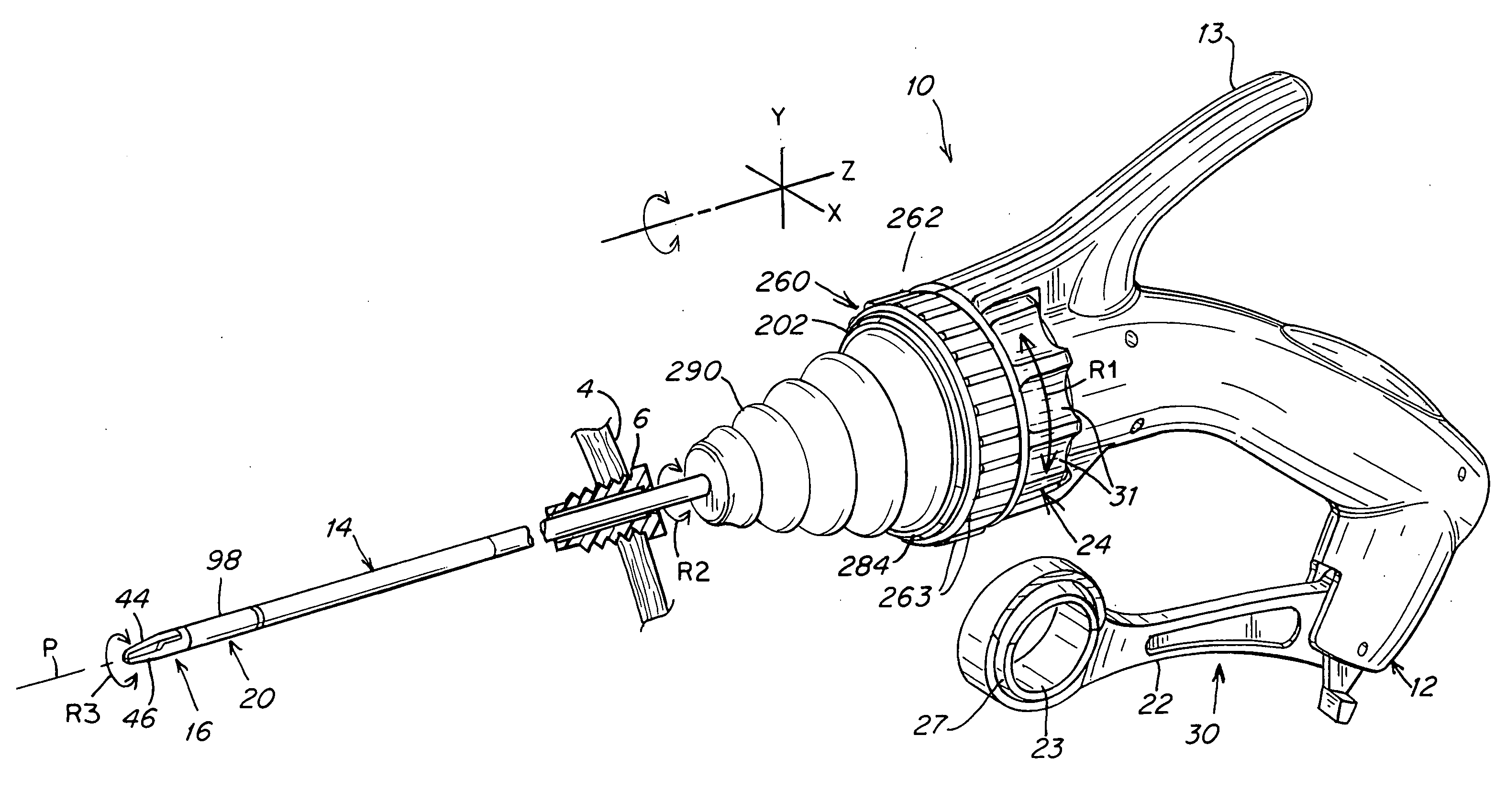
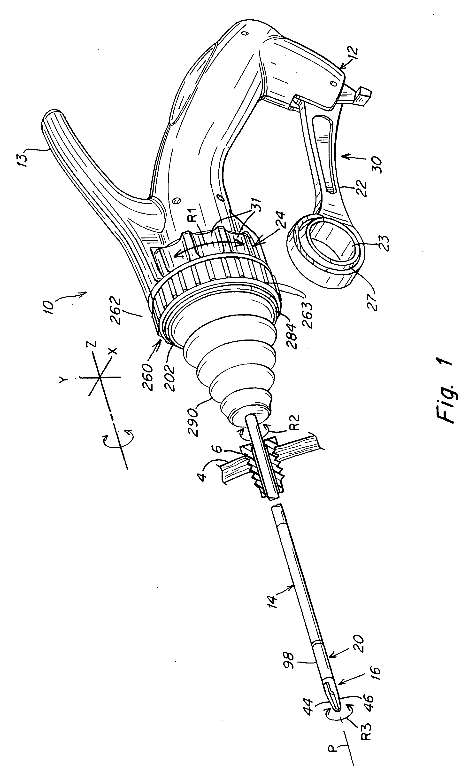
[0065]FIG. 1 is a perspective view of the surgical instrument 10 of the present invention. In this surgical instrument both the tool and handle motion members or bendable members are capable of bending in any direction. They are interconnected via cables (preferably four cables) in such a way that a bending action at the proximal member provides a related bending at the distal member. The proximal bending is controlled by a motion or deflection of the control handle by a user of the instrument. In other words the surgeon grasps the handle and once the instrument is in position any motion (deflection) at the handle immediately controls the proximal bendable member which, in turn, via cabling controls a corresponding bending or deflection at the distal bendable member. This action, in turn, controls the positioning of the distal tool.
[0066]The proximal member is preferably generally larger than the distal member so as to provide enhanced ergonomic control. In the illustrated embodimen...
second embodiment
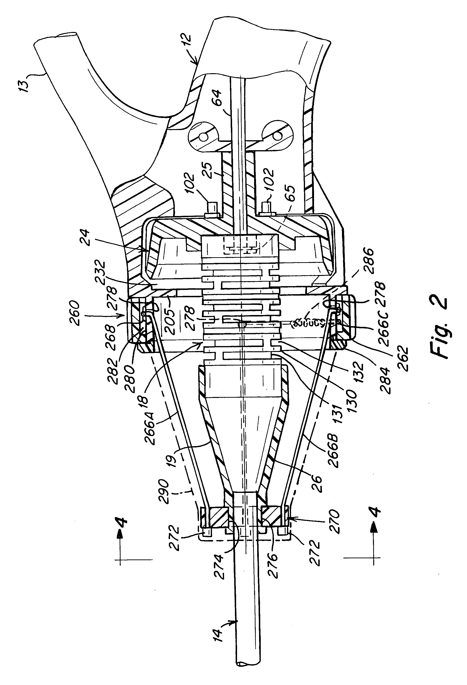
[0104]In this second embodiment, the cables 266 extend from the anchor disk 270 to and over pulleys 296 which are mounted to posts 298 by means of the axles 300. In this regard refer to the cross-sectional views of FIGS. 9 and 10 that illustrate the 90 degree placement of the posts 298. The cable pairs 266A and 266B and the pairs 266C and 266D then pass around a second set of pulleys 302 which are mounted on axles 304 attached to a radial wall 205 of the hub 202. In this regard refer to FIG. 7 which shows the position of the pulley 302 relative to that of the pulley 296. Refer also to FIG. 10 that illustrates both pulleys, with pulleys 302 disposed behind pulleys 296. The cable pairs are connected by springs 306 at end terminals 308 (FIG. 11A). In this embodiment the locking ring 262 has four semi-resilient internal cams 294 that pass through clearance slots 292, as depicted, for example, in FIGS. 10 and 11. These cams 294 pinch the cables 266A-266D against the pulleys 296 and also ...
third embodiment
[0109]In the first two embodiments that are described herein the locking feature includes the use of cabling that is either passed over the hub outer surface or about pulleys. In the instrument, as shown in FIGS. 12-19, the cables 266 have been replaced with rigid rods 316 which provide a stiffer angle locking arrangement since, not only are the lengths of the rods 316 locked in place, but also the angles of the rods 316 are locked in place. This, along with the use of an anchor disc 310, provides a stable platform for the locking feature. The locking is provided primarily by the locking ring 262 which is of somewhat different construction than the locking rings described in the earlier embodiments. The locking ring 262 also uses a cam arrangement for locking the rigid rods at a locked position.
[0110]Each of the rigid rods 316A-316D has a proximal free end and an end pivot ball 318 at the opposite end. The anchor disk 310 has four spherical sockets 314 that receive the respective ba...
PUM
 Abstract
Description
Claims
Application Information
 - R&D
- Intellectual Property
- Life Sciences
- Materials
- Tech Scout
- Unparalleled Data Quality
- Higher Quality Content
- 60% Fewer Hallucinations
Browse by: Latest US Patents, China's latest patents, Technical Efficacy Thesaurus, Application Domain, Technology Topic, Popular Technical Reports.
© 2025 PatSnap. All rights reserved.Legal|Privacy policy|Modern Slavery Act Transparency Statement|Sitemap|About US| Contact US: help@patsnap.com


