Disposable burr attachment

a burr attachment and disposable technology, applied in the field of surgical cutting instruments, can solve the problems of less desirable scenario, less cost effective, and additional time that the curved burr attachment can be in continuous use in a medical procedure, and achieve the effect of attenuating vibrations

Active Publication Date: 2010-11-11
DEPUY SYNTHES PROD INC
View PDF6 Cites 16 Cited by
  • Summary
  • Abstract
  • Description
  • Claims
  • Application Information

AI Technical Summary

Benefits of technology

[0010]A feature of this invention is to provide a coil wire mounted in a support tube that surrounds the wire-shaft of the burr attachment such that it prevents kinking when the burr attachment is bent and it serves to provide heat transfer from the wire shaft to the inner diameter of the support tube surrounding the coil wire and provides a means for migrating grease from the distal end of the support tube upwardly toward the proximal end for lubricating the wire-shaft. T

Problems solved by technology

It is readily understood that this is a less desirable scenario because it is less cost effective.
Distributing the heat dissipation load in this manner reduces the heat or slows down the heat at the cutter resulting in additional time that the Curved Burr Attachmen

Method used


Image

  • Disposable burr attachment
  • Disposable burr attachment
  • Disposable burr attachment

Examples


Embodiment Construction

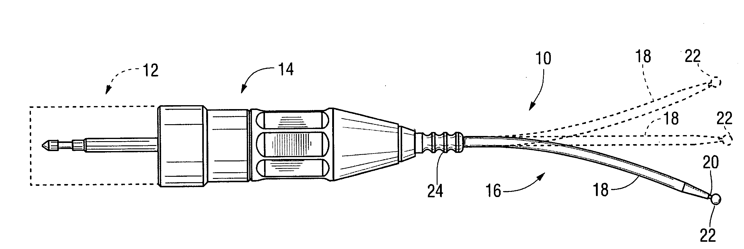
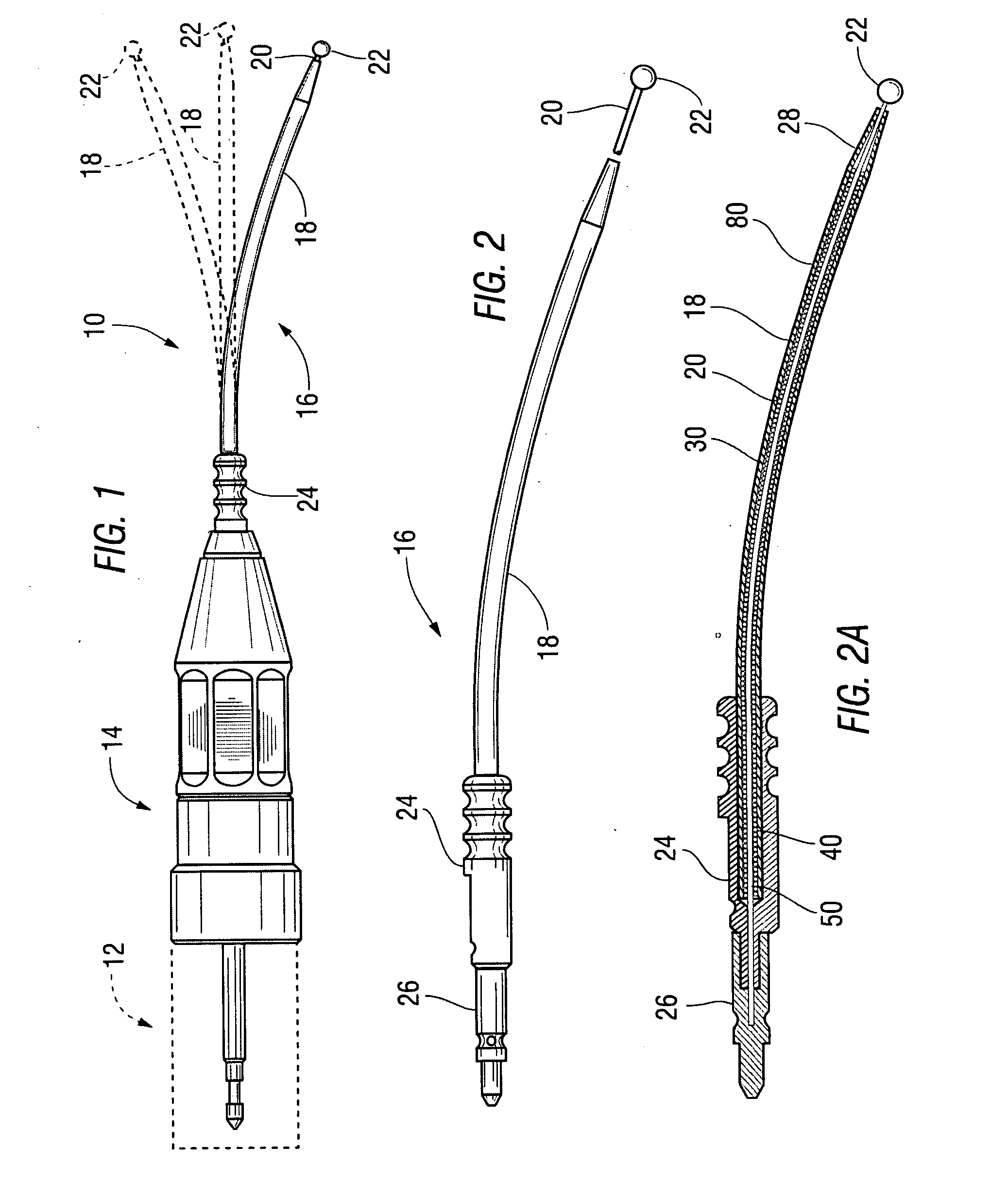
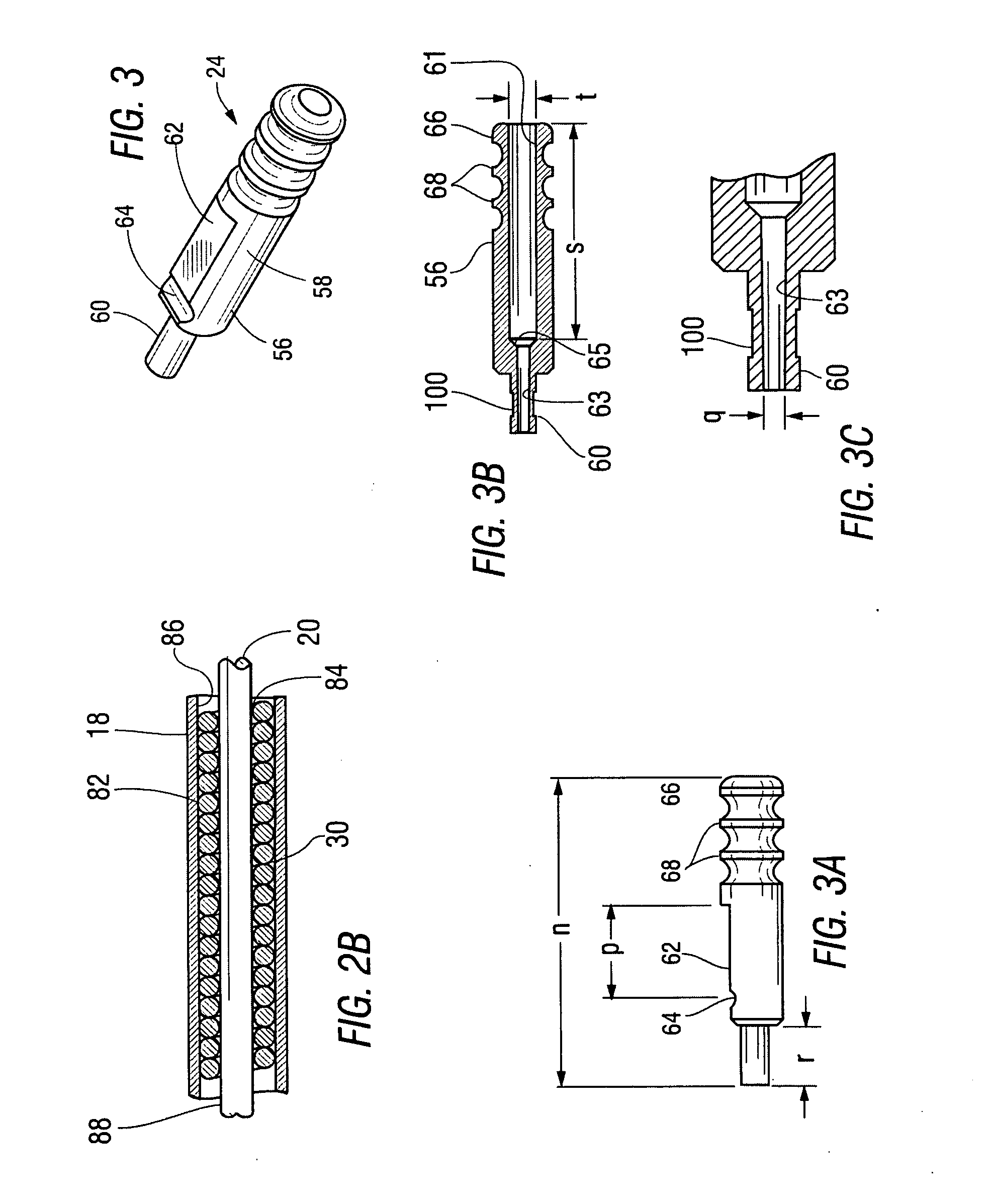
[0031]It will be noted that in the description of the elements of this invention as shown in each of the Figs. in this patent application may be out of proportion with respect to the overall picture of the inventive unit. As for example, some of the elements are shown in a small size and some of the elements are shown in an enlarged size. The purpose, obviously, is to more clearly define the invention and better describe the function of each of the elements. It is to be understood by those skilled in this art that the drawings are not manufacturing drawings, but are drawings used to illustrate the invention and to teach the concept and the workings thereof. Moreover, while the burr attachment of this invention is disclosed as being capable of use in a particular adapter, it is to be understood that other adapters can be used without departing from the scope of this invention and that this invention, amongst other things, teaches the concept of making the burr attachment, per se, dis...


PUM


Abstract

A burr attachment designed for use with a Curved Burr Attachment or other chuck attachments that includes a tube with a wire shaft supported therein and a coil spring surrounding said wire shaft and having each of the coils touch the outer periphery surface of the wire shaft and the inner peripheral surface of said tube to enhance cooling of said outer periphery of said tube from the heat generated by said wire shaft and attenuate vibrations while allowing said burr attachment to be bent without kinking. The burr attachment includes a proximal end support and a distal end support formed on the end of said burr attachment wherein the wire shaft is affixed to said proximal end support and rotates relative to said distal end support and includes detents formed on each of the supports for engaging balls in said adapter so as to be operatively connected thereto when the burr attachment is aligned in said adapter to couple the burr attachment to said Curved Burr Attachment or other chuck attachments for rotary motion of said wire shaft and locating the cutter of said burr attachment to a precise location relative to the end of the Curved Burr Attachment or other chuck attachments. A dimple and annular groove are formed in the proximal end support and distal end support respectively to avoid the cutter from being inadvertently dislodged. A significant purpose of the burr attachment is that it is disposable while the chuck or the adapter of the Curved Burr Attachment is re-usable.

Description

RELATED APPLICATIONS[0001]This invention relates to the patent application concurrently filed and entitled SURGICAL DRILL WITH CURVED BURR ATTACHMENT AND METHOD (Attorney Docket N1350) filed by the same inventors and assigned to the same assignee and incorporated in its entirety herein.FEDERALLY SPONSORED RESEARCH OR DEVELOPMENT[0002]Not applicableTECHNICAL FIELD[0003]This invention relates to a surgical cutting instrument (Curved Burr Attachment) and particularly to a portable and disposable burr attachment capable of use with the Curved Burr Attachment. The burr attachment of this invention has the ability to utilize different sized ball cutters primarily used for cutting bone and being capable of changing the angle of the attachment to different angles to fit into minute curved portions of the anatomy, as for example, the middle ear, although this surgical drill can be utilized for other surgical procedures.BACKGROUND OF THE INVENTION[0004]This invention is particularly efficacio...

Claims


Application Information

Patent Timeline
IPC IPC(8): A61B17/56
CPCA61B17/1617A61B17/162A61B17/1688A61B17/1679A61B17/1631
Inventor DEL RIO, EDDY H.PERRY, DOUGLAS A.
Owner DEPUY SYNTHES PROD INC
Why Eureka
Try Eureka