Methods relating to gas turbine control and operation

a technology of gas turbine and control device, which is applied in the direction of machines/engines, instruments, analogue processes for specific applications, etc., can solve the problems of reducing affecting the efficiency of the turbine engine, etc., and achieves the effect of increasing the engine output and/or the maximum level of engine outpu

Active Publication Date: 2010-11-11
GENERAL ELECTRIC CO
View PDF10 Cites 67 Cited by
  • Summary
  • Abstract
  • Description
  • Claims
  • Application Information

AI Technical Summary

Benefits of technology

[0006]The present application thus describes a method of controlling variable extraction flow in a turbine engine that includes a compressor, a combustor and a turbine, wherein extraction flow comprises a supply of compressed air extracted from the compressor and supplied to the turbine while bypassing the combustor through one or more extraction conduits, and wherein at least one of the extraction conduits includes a variable extraction orifice that has a plurality of settings controlled by a control unit, the method comprising the steps of measuring a plurality of turbine engine operating parameters, wherein the measured operating parameters include at least one associated with a temperature within the turbine, one associated with the setting of the variable extraction orifice, one associated with a pressure within the compressor, one associated with the pressure within one of the extraction conduits, and one associated with the level of extraction flow; monitoring, by the control unit, the measured operating parameters of the combustion turbine engine; calculating, by the control unit, at least one calculated operating parameter based upon model-based control and the measured operating parameters, including at least a measured critical pressure ratio; and manipulating the setting for at least one of the variable extraction orifices such that a decreased and/or minimum extraction flow is determined by comparing whether the measured critical pressure ratio exceeds a scheduled critical pressure ratio.
[0007]The present application further descri...

Problems solved by technology

This extraction comes at a price, however, as the usage of compressor air in this manner decreases the efficiency of the turbine engine.
However, even where variable extr...

Method used


Image

  • Methods relating to gas turbine control and operation
  • Methods relating to gas turbine control and operation
  • Methods relating to gas turbine control and operation

Examples


Embodiment Construction

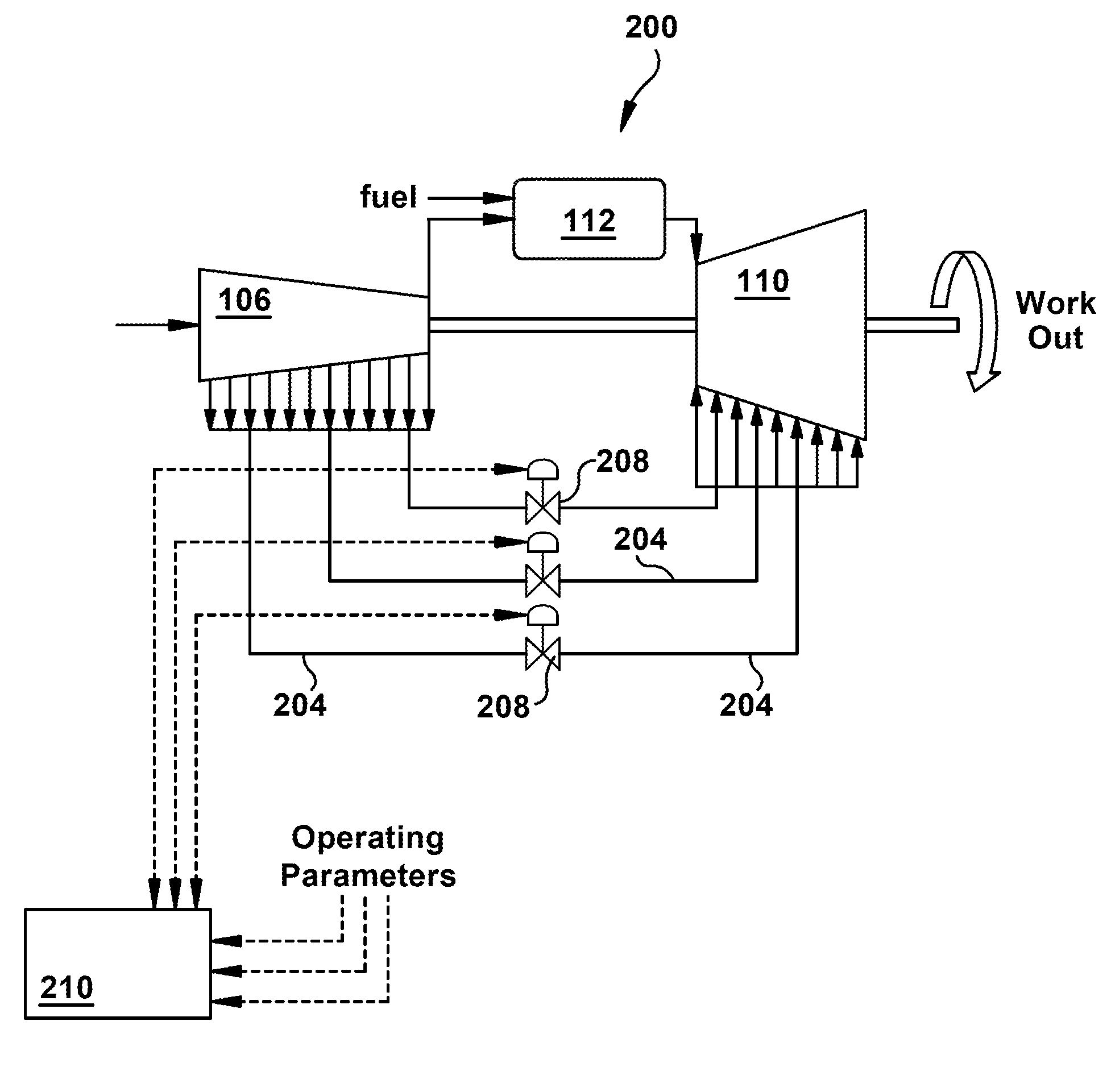
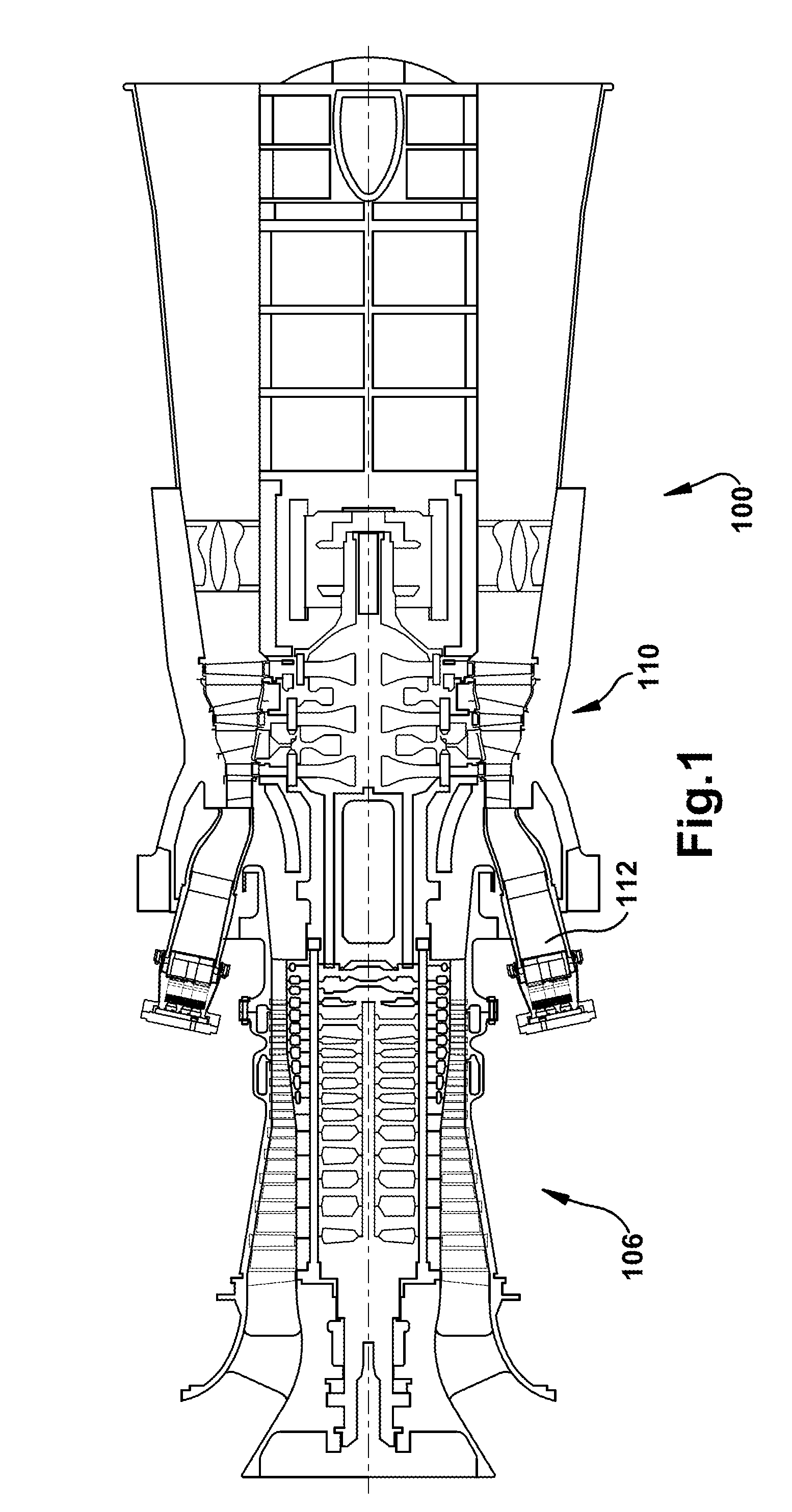
[0016]Referring now to the figures, FIG. 1 illustrates a schematic representation of a gas turbine engine 100, which will be used to describe an exemplary environment in which the present invention may be employed. It will be understood by those skilled in the art that the present invention is not limited to this type of usage. As stated, the present invention may be used in other types of gas turbine engines. In general, gas turbine engines operate by extracting energy from a pressurized flow of hot gas that is produced by the combustion of a fuel in a stream of compressed air. As illustrated in FIG. 1, gas turbine engine 100 may be configured with an axial compressor 106 that is mechanically coupled by a common shaft or rotor to a downstream turbine section or turbine 110, and a combustor 112 positioned between the compressor 106 and the turbine 110.

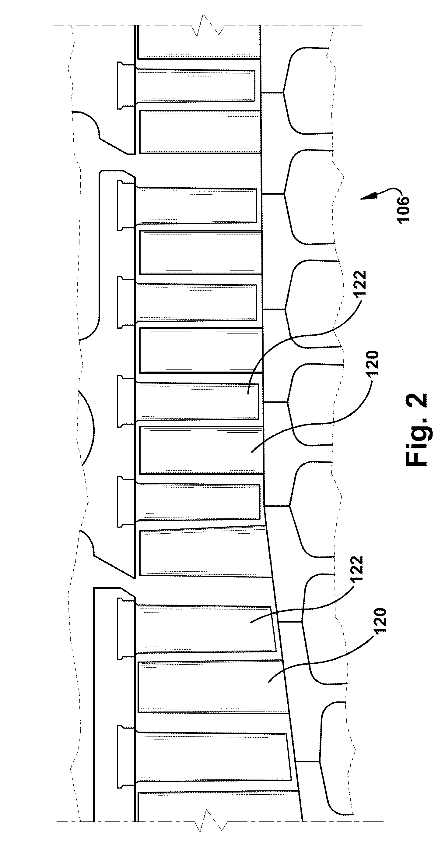
[0017]FIG. 2 illustrates a view of an exemplary multi-staged axial compressor 106 that may be used in the gas turbine engine of FIG. ...


PUM


Abstract

A method of controlling variable extraction flow in a combustion turbine engine, wherein extraction flow comprises a supply of compressed air extracted from the compressor and supplied to the turbine through extraction conduits, and wherein the extraction conduits includes a variable extraction orifice, the method comprising the steps of: measuring a plurality of turbine engine operating parameters; monitoring, by a control unit, the measured operating parameters of the combustion turbine engine; setting the variable extraction orifices to a setting that allows an approximate maximum level of extraction flow; calculating, by the control unit, at least one calculated operating parameter based upon model-based control and the measured operating parameters, including at least a current turbine inlet temperature and a maximum turbine inlet temperature; and manipulating the setting for the supply of fuel to the combustor such that an increased and/or maximum level of engine output is determined by comparing the values for the current turbine inlet temperature and the maximum turbine inlet temperature.

Description

BACKGROUND OF THE INVENTION[0001]This present application relates generally to methods, systems, and / or apparatus for improving the efficiency and / or operation of gas turbine engines, which, as used herein and unless specifically stated otherwise, is meant to include all types of gas or combustion turbine or rotary engines, including aircraft engines, power generating engines and others. More specifically, but not by way of limitation, the present application relates to methods, systems, and / or apparatus pertaining to controlling compressor extraction flows during operation to improve engine performance.[0002]In general, gas turbine engines include a compressor, a combustor, and a turbine. The compressor and turbine generally include rows of blades that are axially stacked in stages. Each stage includes a row of circumferentially-spaced stator blades, which are fixed, and a row of rotor blades, which rotate about a central axis or shaft. In operation, generally, the compressor rotor...

Claims


Application Information

Patent Timeline
IPC IPC(8): F02C9/18F02G3/00F02C6/08
CPCF02C6/08F02C9/18F05D2270/3032F05D2270/301F05D2270/44
Inventor CHILDERS, SCOTT A.
Owner GENERAL ELECTRIC CO
Why Eureka
Try Eureka