Landing gear shock absorber with variable viscosity fluid

a technology of fluid and viscosity, applied in the direction of shock absorbers, mechanical equipment, transportation and packaging, etc., can solve the problem of structural failure of shock absorbers before much energy is absorbed

Inactive Publication Date: 2002-11-05
JAUNT AIR MOBILITY LLC
View PDF20 Cites 46 Cited by
  • Summary
  • Abstract
  • Description
  • Claims
  • Application Information

AI Technical Summary

Problems solved by technology

Most prior art shock absorbing systems have the characteristic that high forces associated with hard or crash landings will structurally fail the shock absorbers before much energy is absorbed.
The pressure also is limited to a desired maximum level so that, in a severe crash, the shock absorber will absorb significant energy before it fails structurally.

Method used


Image

  • Landing gear shock absorber with variable viscosity fluid
  • Landing gear shock absorber with variable viscosity fluid
  • Landing gear shock absorber with variable viscosity fluid

Examples


Embodiment Construction

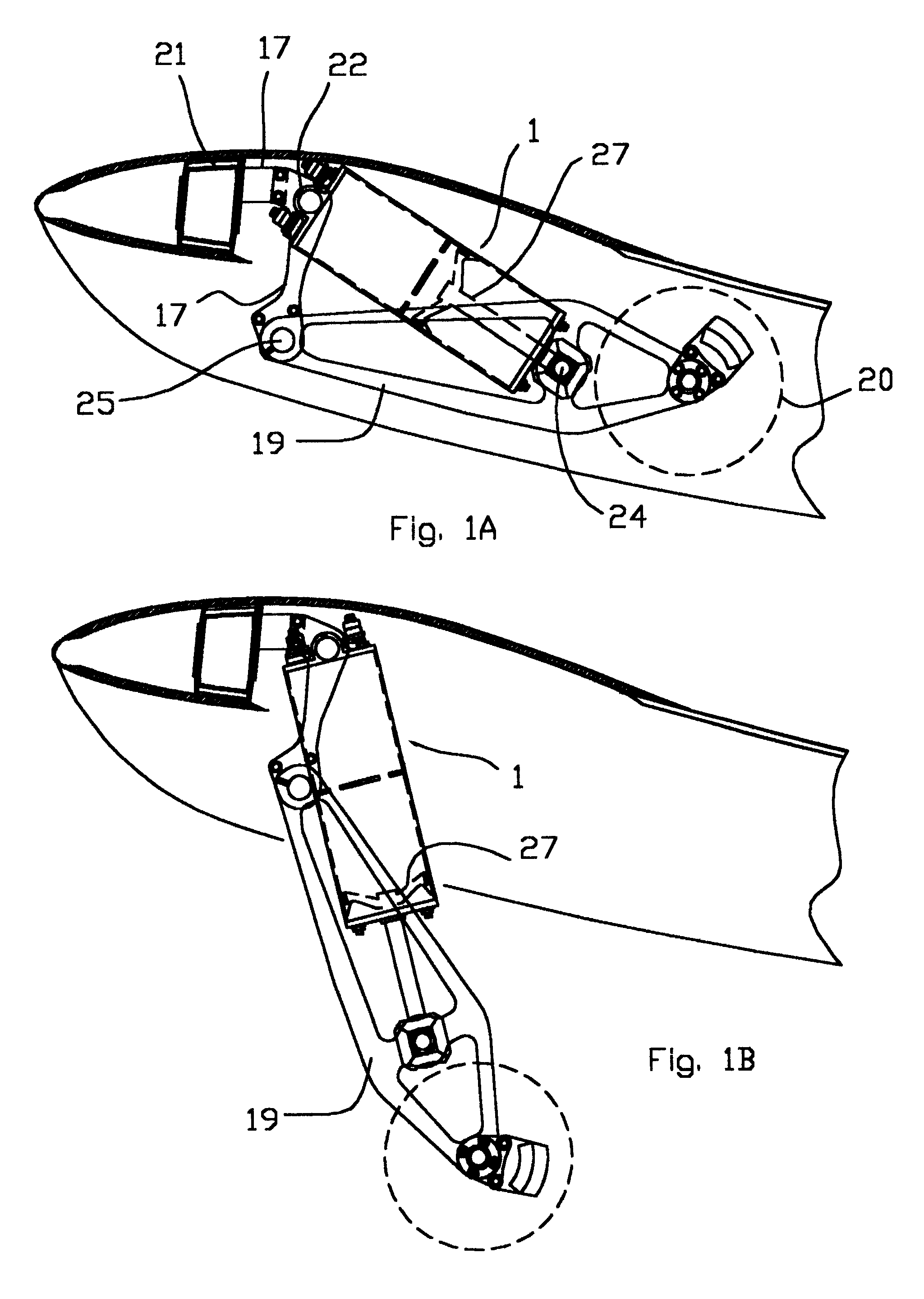
FIG. 1a shows a side view cross section of a cylinder assembly 1 with the landing gear retracted. In the embodiment shown, landing gear leg 19 with wheel 20 is pivotably attached by bearing 25 to wing spar 21. Cylinder assembly 1 is pivotally attached to wing spar 21 by bushing 22 and to landing gear leg 19 by bushing 24. FIG. 1b shows a side view cross section of the cylinder assembly 1 with the landing gear extended. Contrasting FIGS. 1a and 1b, respectively, piston 27 is fully inserted within cylinder assembly 1 with landing gear leg 19 in the retracted position, and fully withdrawn from cylinder assembly 1 with landing gear leg 19 in the extended position.

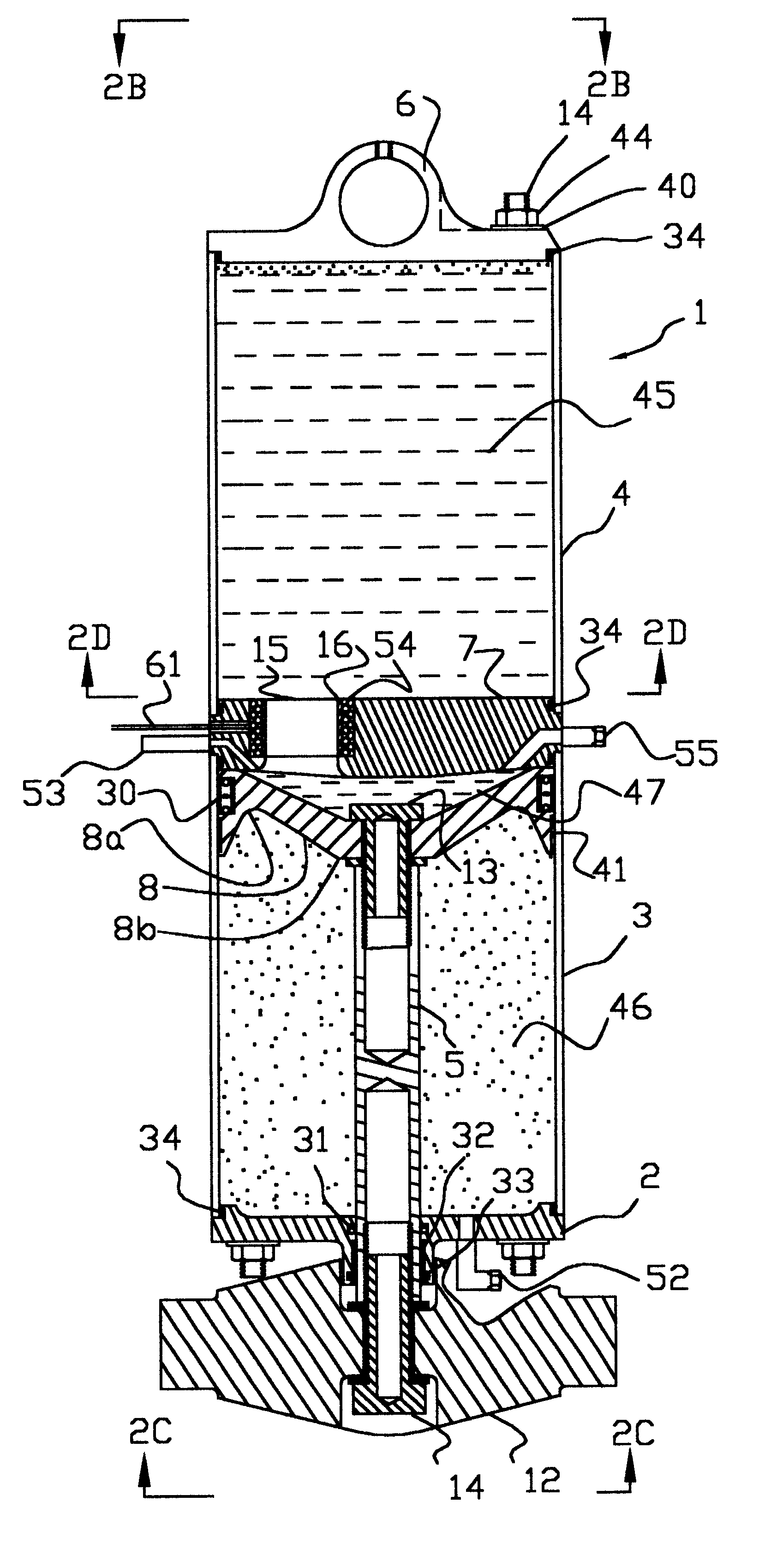
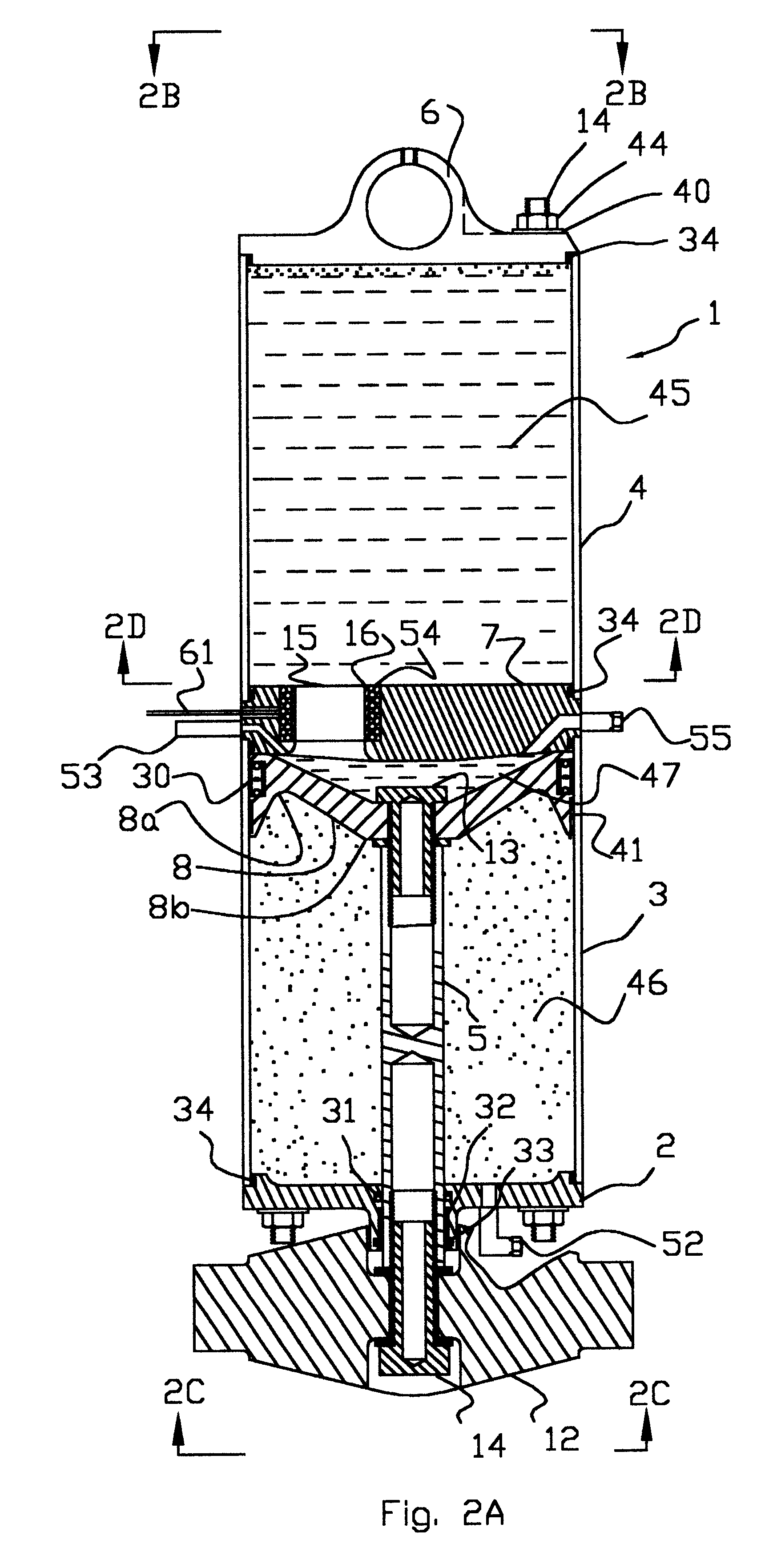
Referring to FIG. 2a, cylinder assembly 1 comprises a lower cylinder 3 and an upper cylinder 4 that are separated and sealed by cylinder head 7. Top cap 6 seals the top of upper cylinder 4 and provides an attachment for a shaft (not shown) on which the cylinder assembly 1 pivots and attaches to the airframe. Bottom cap 2 seals ...


PUM


Abstract

An aircraft landing gear includes a sealed cylinder divided by a cylinder head to define an upper chamber and a lower chamber. The lower chamber is further divided by a piston having a piston rod passing in a sealed manner through the lower cylinder end. The cylinder head includes one or more orifices, the opening of each containing an electromagnetic coil configured to control the viscosity of the magneto-rheological oil passing therethrough. The electrical current through the electromagnetic coil is continually controlled by a microcomputer with attached sensors for piston position and pressure between the desired piston and the cylinder head, such that the pressure between the piston and the cylinder head decelerates the aircraft evenly throughout the desired piston stroke. The pressure also is limited to a desired maximum level so that, in a severe crash, the shock absorber will absorb significant energy before it fails structurally.

Description

1. Technical FieldThe present invention generally relates to an improved landing gear retraction and shock absorption system having an air over oil shock absorber wherein the oil is magneto-rheological.2. Description of the Prior ArtVarious combinations of springs and shock absorbers are known to absorb the landing energy of aircraft and provide suspension. Electric, hydraulic, or pneumatic systems have been used to extend and retract landing gear, in some cases using the shock absorbing cylinder as an actuator. Most prior art shock absorbing systems have the characteristic that high forces associated with hard or crash landings will structurally fail the shock absorbers before much energy is absorbed. As a result, the aircraft structure itself and the passengers absorb the crash forces. Other prior art designs absorb crash forces by permanently deforming a portion of the shock absorbing device.U.S. Pat. No. 5,944,283 describes a system that utilizes the difference between the inter...

Claims


Application Information

Patent Timeline
Patent Type & Authority Patents(United States)
IPC IPC(8): B64C25/00B64C25/60F16F9/53
CPCB64C25/60F16F9/535
Inventor CARTER, JR., JAY W.
Owner JAUNT AIR MOBILITY LLC
Why Eureka
Try Eureka