
Method for compensating measurement errors caused by deformations of a measuring machine bed under the load of a workpiece and measuring machine operating according to said method

Active Publication Date: 2010-11-11
HEXAGON METROLOGY SPA
View PDF7 Cites 57 Cited by
  • Summary
  • Abstract
  • Description
  • Claims
  • Application Information

AI Technical Summary

Benefits of technology

[0009]The present invention likewise regards a measuring machine operating according to said method.

Problems solved by technology

Current compensation techniques, of a strictly geometrical nature, do not generally take into account the measurement errors deriving from the elastic deformations of the machine bed under the weight of the workpiece to be measured.
When the workpiece to be measured has a considerable weight (for example, in the case of dies, engine parts, castings of large dimensions) said errors may be non-negligible and jeopardize the accuracy of the machine.

Method used


Image

  • Method for compensating measurement errors caused by deformations of a measuring machine bed under the load of a workpiece and measuring machine operating according to said method
  • Method for compensating measurement errors caused by deformations of a measuring machine bed under the load of a workpiece and measuring machine operating according to said method
  • Method for compensating measurement errors caused by deformations of a measuring machine bed under the load of a workpiece and measuring machine operating according to said method

Examples


Embodiment Construction

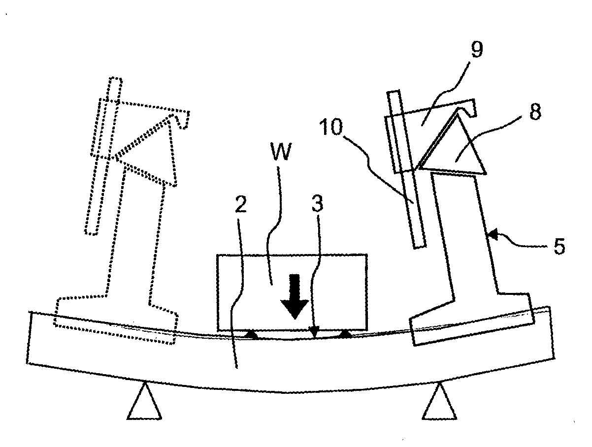
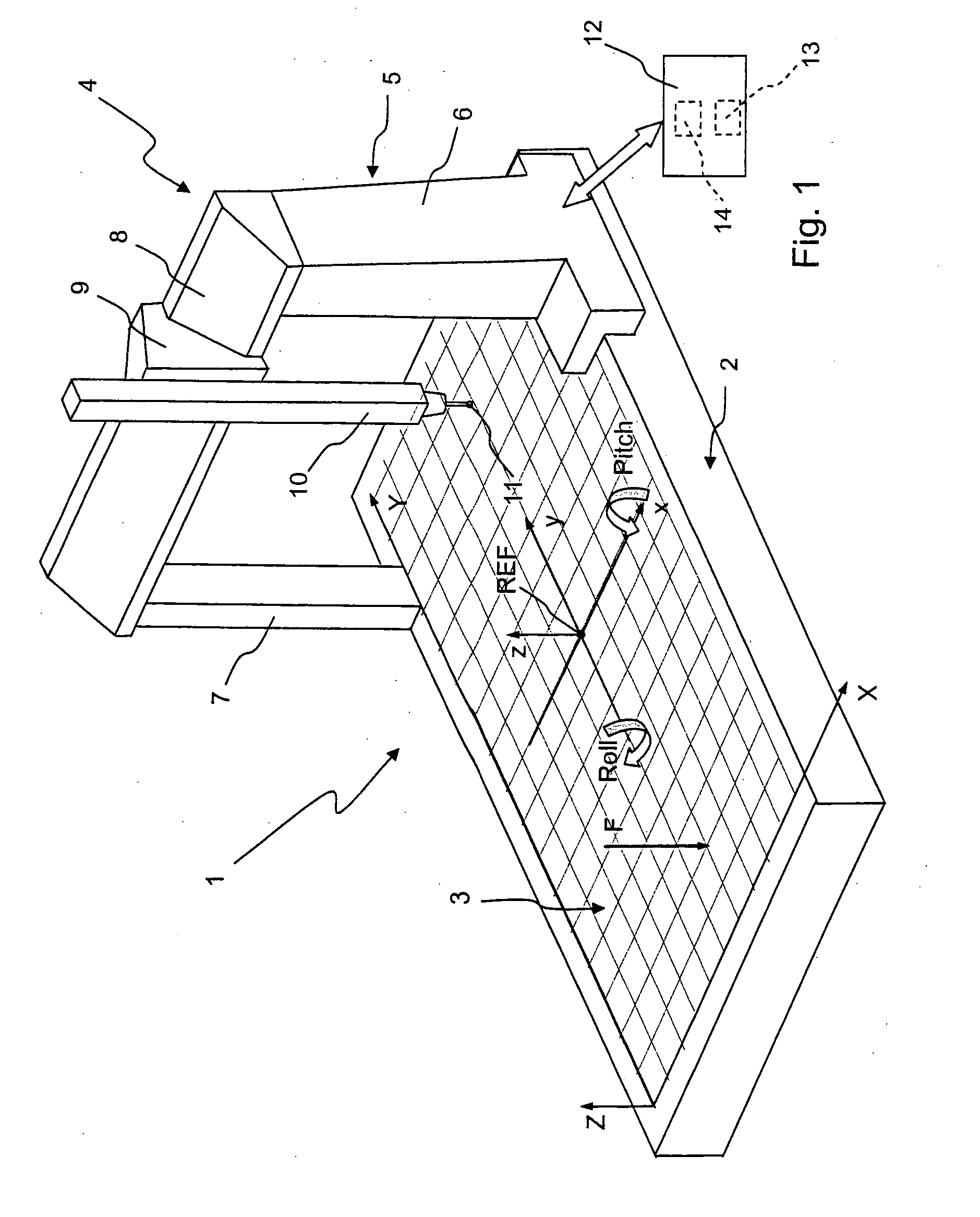
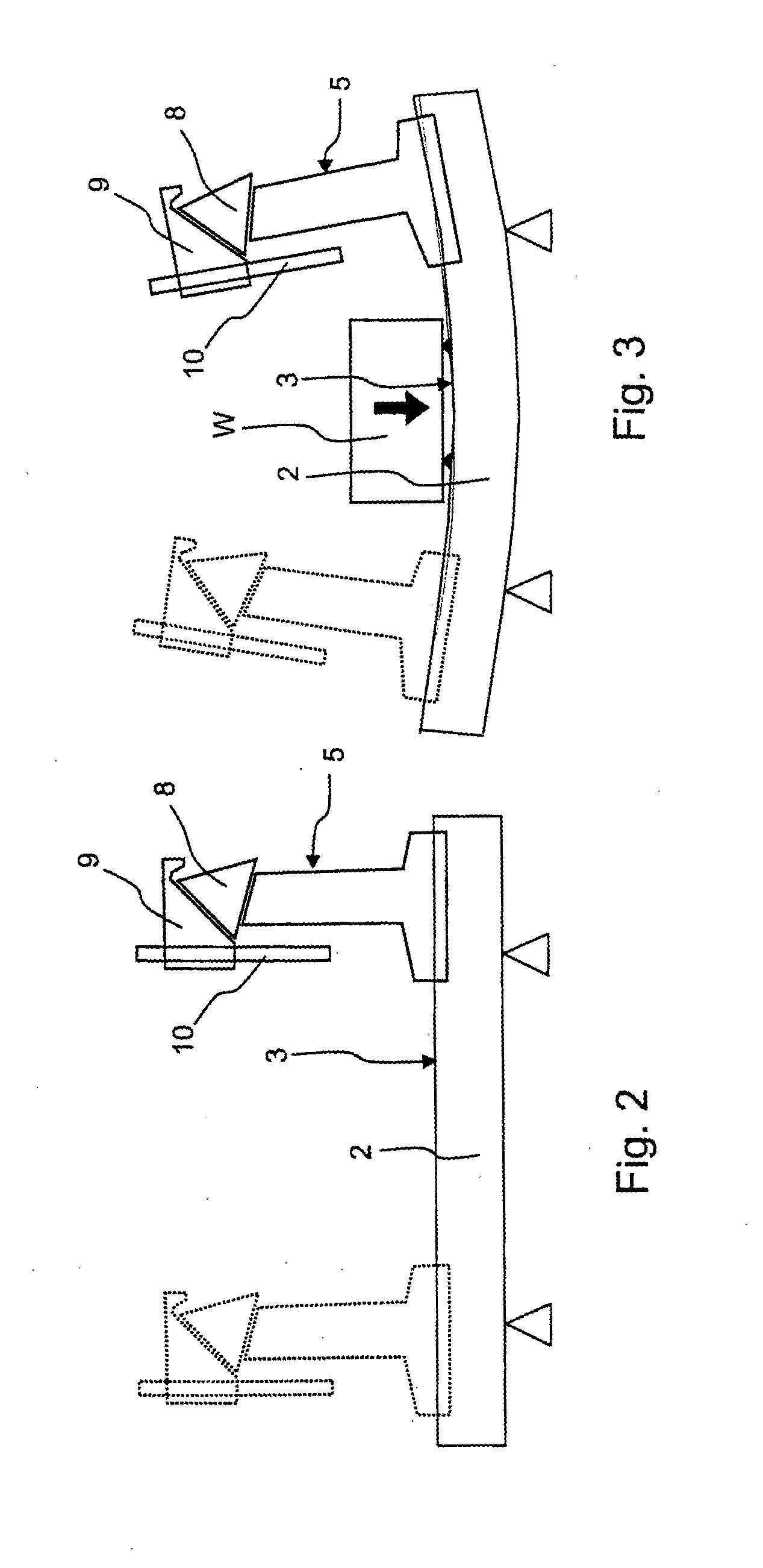
[0018]With reference to FIG. 1, designated as a whole by 1 is a portal measuring machine. It is at once pointed out that the method forming the subject of the present invention can be used for the compensation of the errors of machines of different architecture, for example with horizontal arm or pillars.

[0019]The machine 1 comprises a plane machine bed 2 provided with a horizontal working surface 3 designed to support an object to be measured (not illustrated), and a unit 4, which is mobile with respect to the machine bed 2 along co-ordinate axes.

[0020]The unit 4 comprises a main portal carriage 5 (in what follows, for reasons of brevity, “portal 5”) , which is mobile with respect to the machine bed 2 along a horizontal axis Y. The portal 5 is provided with a pair of uprights 6 and 7 and a cross-member 8 extending between the uprights 6 and 7 in a direction parallel to a horizontal axis X and perpendicular to the axis Y.

[0021]The unit 4 moreover comprises a secondary carriage 9, ca...


PUM


Abstract

A method of compensating the measurement errors of a measuring machine that derive from the deformations of the machine bed caused by the load exerted by the workpiece to be measured on the machine bed, comprising a first acquisition step in which data regarding the weight of the workpiece and the modes of resting of the workpiece on the machine bed are acquired, and a second calculation step in which correction values depending upon said data are calculated.

Description

PRIORITY CLAIM[0001]This application claims priority under 35 U.S.C. 365 AND / OR 35 U.S.C. 119 to PCT application no. PCT / IT2007 / 000521 filed on Jul. 24, 2007.TECHNICAL FIELD[0002]The present invention relates to a method of compensating the measurement errors of a measuring machine deriving from the deformations of the machine bed caused by the load exerted by the workpiece to be measured on the machine bed, as well as to a measuring machine operating according to said method.BACKGROUND ART[0003]As is known, measuring machines are generally provided with a fixed base or machine bed and a mobile unit designed to move a measuring head according to co-ordinate axes with respect to the machine bed in a measurement space located above the machine bed. The mobile unit generally comprises a main carriage, which is mobile along an axis that is longitudinal with respect to the machine bed, and one or more carriages carried by the main carriage, which are mobile along respective co-ordinate a...

Claims


Application Information

Patent Timeline
IPC IPC(8): G06F19/00
CPCG01B5/0016G01B21/045G01B5/008G01B21/04G01B21/042
Inventor MERLOT, LORENZO
Owner HEXAGON METROLOGY SPA
Learn More