Evaluation of the integrity of depressed contacts by variation of the rotation of the pole-shaft

a technology of depressed contacts and rotational rotation, which is applied in the field of evaluation of the erosion of contacts, can solve the problems of affecting the safety and availability of installation, the failure of the switchgear device, and the inability to operate normally

Active Publication Date: 2010-11-18
SCHNEIDER ELECTRIC IND SAS
View PDF23 Cites 20 Cited by
  • Summary
  • Abstract
  • Description
  • Claims
  • Application Information

AI Technical Summary

Benefits of technology

[0007]Among other advantages, the object of the invention is to provide a device for checking the integrity of the contacts that is simple and suitable for

Problems solved by technology

After a large number of switching operations, this wear can lead to malfunctioning of the switchgear device, with consequences on the safety and availability of the installation.
These operations are however often performed either too late, for example if one of the switching operations has generated a greater electric arc, with the related risks, or too early, with the costs inherent to replacement of pads that show hardly any wear.
Visual checking of the contacts at preset interv

Method used


Image

  • Evaluation of the integrity of depressed contacts by variation of the rotation of the pole-shaft
  • Evaluation of the integrity of depressed contacts by variation of the rotation of the pole-shaft
  • Evaluation of the integrity of depressed contacts by variation of the rotation of the pole-shaft

Examples


Embodiment Construction

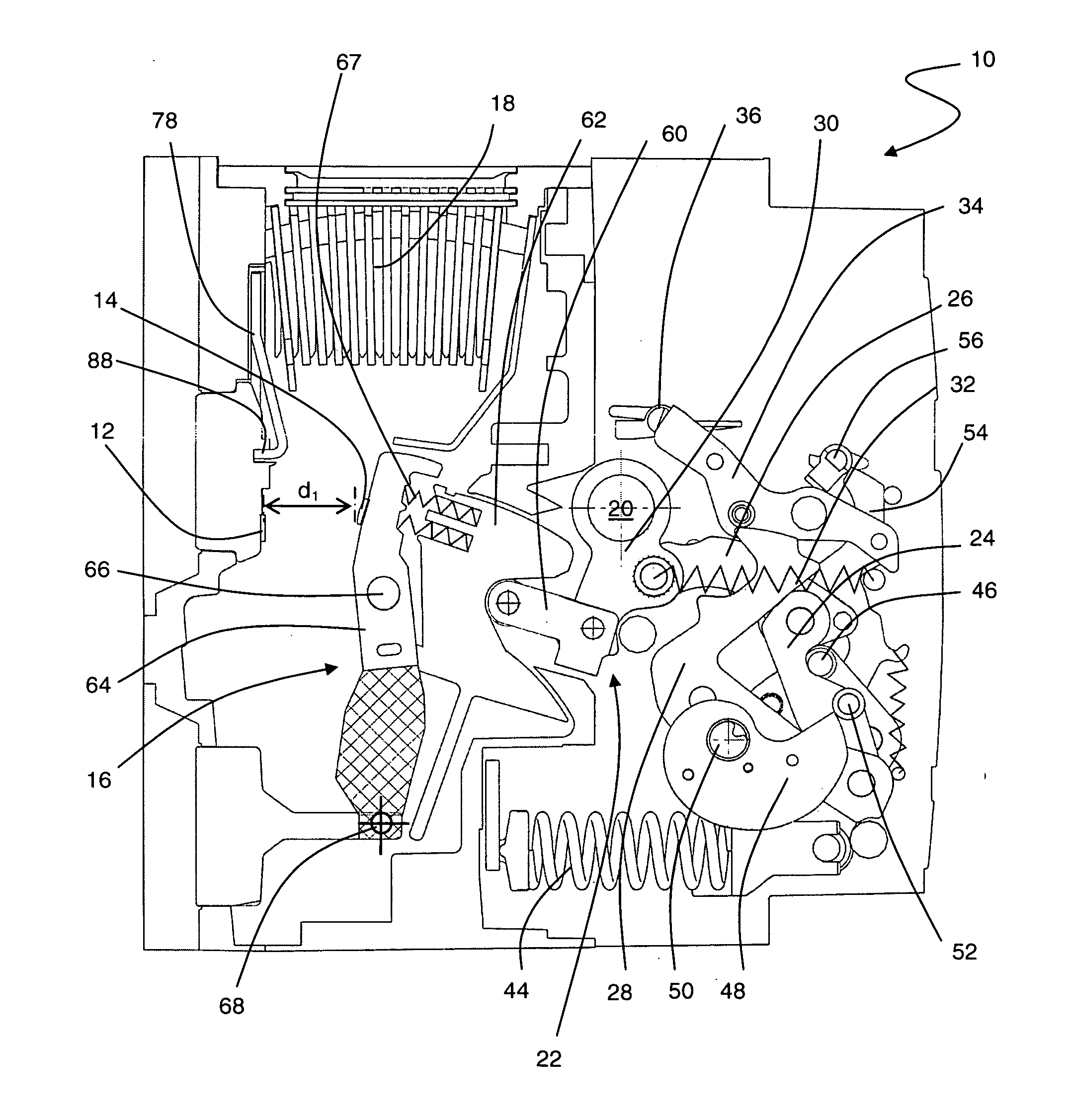
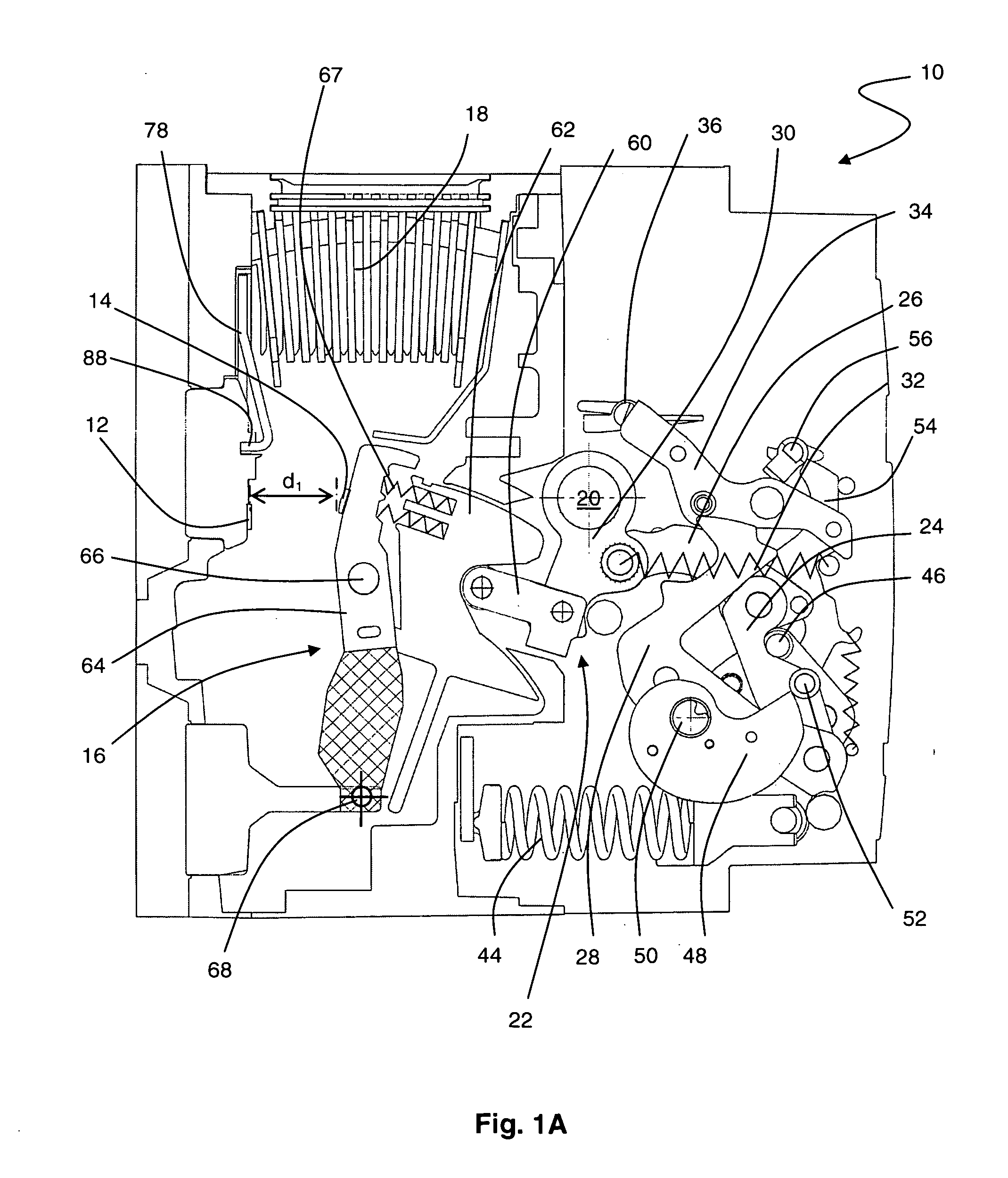
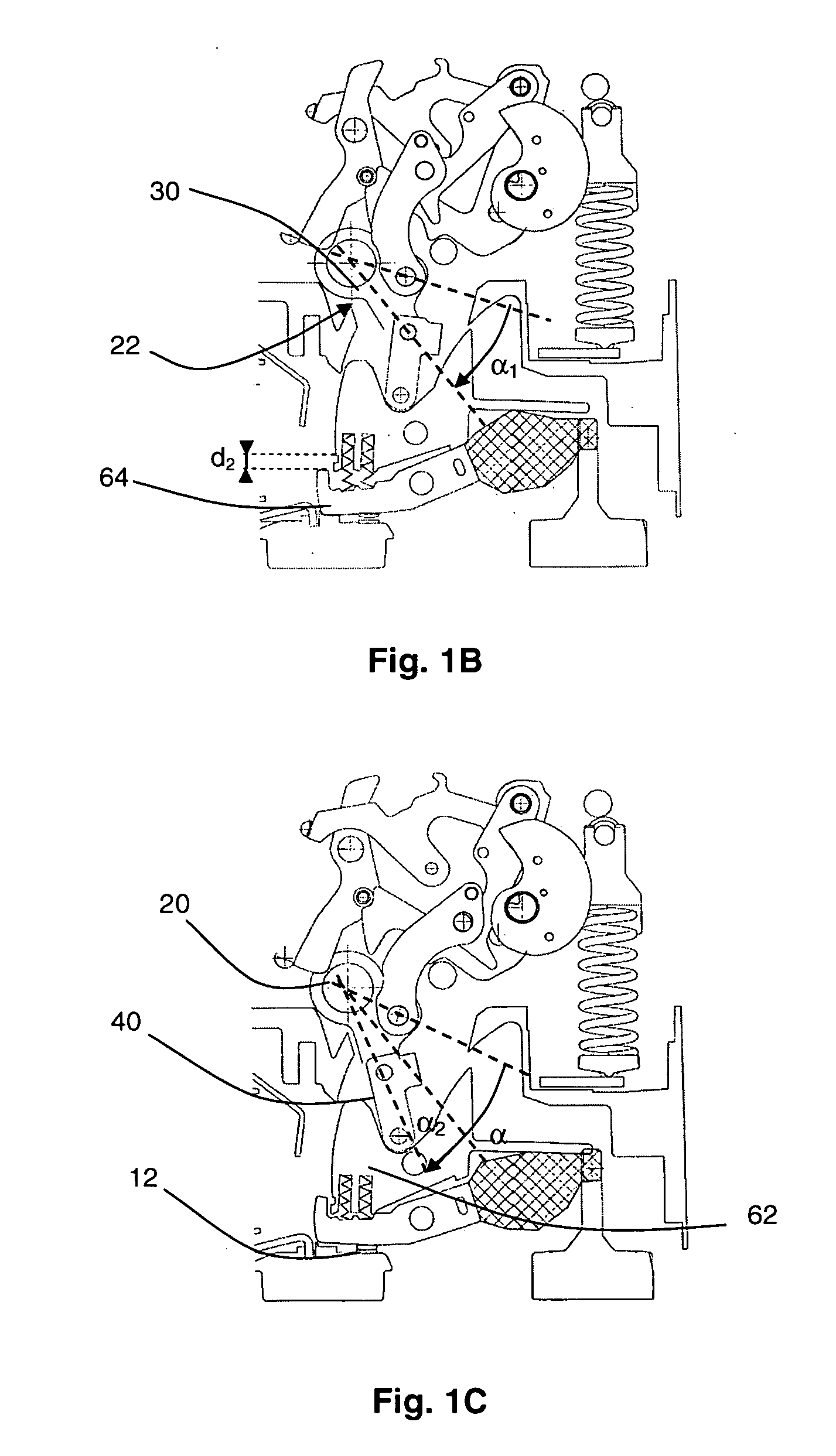
[0017]With reference to FIG. 1A and in conventional manner, a circuit breaker 10 for high currents, in excess of 800 A comprises a pair of breaking contacts, or main contacts, for each pole-unit. Each main contact is preferably associated with a pad 12, 14 made from suitable material, for example from a silver-based alloy, and one of the pads 14 is fitted on an arm 16 pivoting between an open position wherein it is away from the stationary contact 12 and a closed position wherein mechanical and electrical contact between the pads 12, 14 is established. The pole-unit also comprises an arc extinguishing chamber 18 and a pair of main terminals (not shown) designed to plug into connection strips. For these high-rating ranges, the circuit breaker 10 comprises a plurality of pole-units arranged in parallel planes, perpendicular to a pole-shaft 20 that is common thereto. The pole-unit closing or opening order is transmitted to each movable contact 14 from the pole-shaft 20 via a drive mech...


PUM


Abstract

A device for measuring the wear of the contacts of a switchgear device is described. The switchgear device is of the open circuit breaker type with offset pole-shaft, and the movable contact is mounted on a sliding support. Measurement of the wear of the contacts is based on evaluation of the over-travel of the movable contact in the closed position when the latter slides in its support. This over-travel is determined by measuring the residual rotation of the pole-shaft, preferably by a contact-less magnetic rotation sensor.

Description

TECHNICAL FIELD[0001]The invention relates to evaluation of the erosion of the contacts of pole-units in a switchgear device by indirect measurement of the rotational movement of a driving mechanism of the contacts. In particular, the invention relates to a switchgear device comprising a pair of contacts that are movable with respect to one another, the movable contact being supported by an arm that allows it to perform an over-travel in the closed position. The invention also relates to a method for providing for a high electrodynamic strength switchgear device to be equipped with means enabling the integrity of the contacts to be checked.STATE OF THE ART[0002]A power line supplying an electric load to be controlled is conventionally provided with at least one switchgear device which, for each phase, comprises pairs of contacts that are movable with respect to one another to switch the load. Actuation of the contacts can be performed in different ways; in particular, for some high-...

Claims


Application Information

Patent Timeline
IPC IPC(8): H01H1/50H01H1/36
CPCH01H1/0015H01H1/225H01H11/0062H01H2071/048H01H71/526H01H2071/044H01H71/04
Inventor RIVAL, MARC
Owner SCHNEIDER ELECTRIC IND SAS
Why Eureka
Try Eureka