Combined RGB and IR Imaging Sensor

a technology of imaging sensor and rgb, which is applied in the direction of television system, solid-state device signal generator, picture signal generator, etc., can solve the problems of affecting the color reproduction of images, increasing the cost of lenses, and affecting the use of automotive or consumer digital cameras or cell phone cameras,

Active Publication Date: 2010-11-18
MAGNA ELECTRONICS
View PDF11 Cites 178 Cited by
  • Summary
  • Abstract
  • Description
  • Claims
  • Application Information

AI Technical Summary

Benefits of technology

This patent describes an image sensor that can capture both color and IR light through its pixels. It uses special methods called demosacing to process these images. This type of sensor has many applications including car safety features like headlamps controls, reversed aid systems, and others. It could also find use in other areas like security cameras, mobile phones, and industrial machines.

Problems solved by technology

The patent text discusses the problem of IR contamination in color imagers and the need for an IR cut-off filter to reduce this contamination. However, traditional IR cut-off filters increase the cost of the lens and are not suitable for automotive or consumer digital cameras. The technical problem is to provide a cost-effective solution for reducing IR contamination without compromising the quality of the image.

Method used


Image

  • Combined RGB and IR Imaging Sensor
  • Combined RGB and IR Imaging Sensor
  • Combined RGB and IR Imaging Sensor

Examples


Embodiment Construction

Imaging Sensor Description

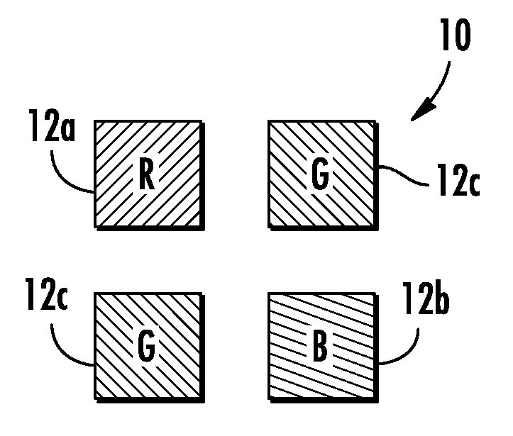
[0020]The imaging sensor of the present invention comprises a two-dimensional pixelated imaging array having a plurality of photo-sensing pixels arranged or disposed or established on a semiconductor substrate. For example, the imaging sensor may comprise a complementary-metal-oxide-semiconductor (CMOS) or a CCD imaging sensor or device or the like, and may utilize aspects of the imaging sensors described in U.S. Pat. Nos. 5,796,094; 6,097,023; 6,320,176; 6,313,454; 6,559,435; 6,831,261; 6,396,397; 5,877,897; 6,498,620; 5,670,935; 6,806,452; 6,946,978; 7,123,168; 7,004,606; 7,005,974; and / or 5,550,677, and / or PCT Application No. PCT / US07 / 75702, filed Aug. 10, 2007, and / or U.S. patent applications, Ser. No. 11 / 239,980, filed Sep. 30, 2005; Ser. No. 11 / 105,757, filed Apr. 14, 2005 by Schofield et al. for IMAGING SYSTEM FOR VEHICLE; and / or Ser. No. 10 / 534,632, filed May 11, 2005; and / or PCT Application No. PCT / US2003 / 036177, filed Nov. 14, 2003 by Donnelly Cor...


PUM


Abstract

An imaging system suitable for use in a vehicle includes an imaging sensor having a two-dimensional array of photosensing elements, an image processor for processing image data captured by the imaging sensor, and a display for displaying images responsive to the image processor. The array has a plurality of sub-arrays, with each of the sub-arrays having a first pixel sensing primarily a first color, a second pixel sensing primarily a second color, a third pixel sensing primarily a third color and a fourth pixel sensing primarily infrared radiation. The image processor processes the output of the fourth pixel to determine an infrared component of the imaged scene and subtracts the infrared component from the outputs of the first, second and third pixels to obtain a more accurate or true color response for the pixels and to limit or avoid infrared color wash-out.

Description


Claims


Application Information

Patent Timeline
Owner MAGNA ELECTRONICS
Why Eureka
Try Eureka