
Automated transient image cytometry

Active Publication Date: 2010-11-18
CHARLOT DAVID J +3
View PDF9 Cites 9 Cited by
  • Summary
  • Abstract
  • Description
  • Claims
  • Application Information

AI Technical Summary

Problems solved by technology

Unfortunately, this is not always the case and researchers are usually forced to either tweak their experimental design or are required to build customized tools to conduct their experiments.

Method used


Image

  • Automated transient image cytometry
  • Automated transient image cytometry
  • Automated transient image cytometry

Examples


Embodiment Construction

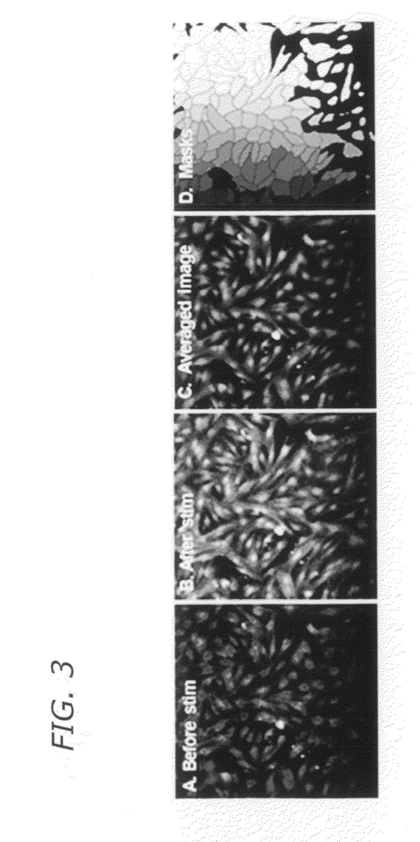
[0022]in order to obtain information about a transient event (like the contractile cycle of cardiomyocytes) on a cell-by-cell basis in an automated image cytometry system, a video stream constituted of time-sequenced magnified images is acquired and an averaged image is obtained from averages of all images in the video stream. The averaged image is segmented to obtain a cell periphery mask. A set of transient data for each cell is obtained by applying the mask to each image of the video stream. For example, but without limiting the scope of application, presume a video stream of magnified images is obtained which is constituted of a time-series sequence of frames containing magnified images of the same field of view showing cells marked with a dye bound to elements active in a transient event. For example, presume that the time-series sequence includes magnified images of fluo-4 loaded cardiac myocytes. With reference to FIG. 3, the time-series sequence of frames includes images A a...


PUM


Abstract

A method, system, and instrument for automatically measuring transient activity in cells uses image time sequences to identify transients in cells. Preferably, the transient activity is stimulated or provoked in synchronism with acquisition of the image time sequences. A cell mask is applied to each image of an image time sequence in order to localize the transient activity with respect to each cell. Localization enables cell-by-cell analysis of properties of the transient activity.

Description

RELATED APPLICATIONS[0001]This Application contains subject matter related to the subject matter of the assignee's U.S. patent application Ser. Nos. 11 / 285,691, filed Nov. 21, 2005, and published as US 2008 / 0144895 A1 on Jun. 19, 2008, and to the PCT counterpart, PCT / 2005 / 044936, filed Nov. 17, 2006, and published as WO 2007 / 061971 A2 on May 31, 2007.STATEMENT OF GOVERNMENT INTEREST[0002]The invention described herein were made in part with government support under Grant No. 1R42HL086076 awarded by the National Institutes of Health. The United States Government has certain rights in the invention.BACKGROUND[0003]The field is processes, systems, and instruments for automatically measuring transient activity in cells using image sequences. More specifically, the field includes use of image cytometry to automatically measure calcium transients in cardiomyocytes.[0004]Automated image cytometry is increasingly used in high content screening (HCS) to automatically measure characteristics ...

Claims


Application Information

Patent Timeline
IPC IPC(8): H04N7/18G06K9/00
CPCG06T7/0016G06T2207/10016G06T2207/10056C12Q1/02G06T2207/20152G06T2207/20216G06T2207/30024G06T2207/10064
Inventor CHARLOT, DAVID J.INGERMANSON, RANDALL S.MCDONOUGH, PATRICK M.PRICE, JEFFREY H.
Owner CHARLOT DAVID J
Learn More