Image display device using variable-focus lens at conjugate image plane

a variable-focus lens and image plane technology, applied in the direction of pulse technique, printer, camera focusing arrangement, etc., can solve the problem of not being able to disclose the location of the variable-focus lens

Active Publication Date: 2010-11-18
BROTHER KOGYO KK
View PDF4 Cites 93 Cited by
  • Summary
  • Abstract
  • Description
  • Claims
  • Application Information

AI Technical Summary

Benefits of technology

[0021]The foregoing summary, as well as the following detailed description of preferred embodiments of the invention, will be better understood when read in conjunction with the appended drawings. For the purpose of illustrating t

Problems solved by technology

The Japan Patent Application Publication No. hei 9-297282, however, fails to disclose that there is a given relation between the size

Method used


Image

  • Image display device using variable-focus lens at conjugate image plane
  • Image display device using variable-focus lens at conjugate image plane
  • Image display device using variable-focus lens at conjugate image plane

Examples


first embodiment

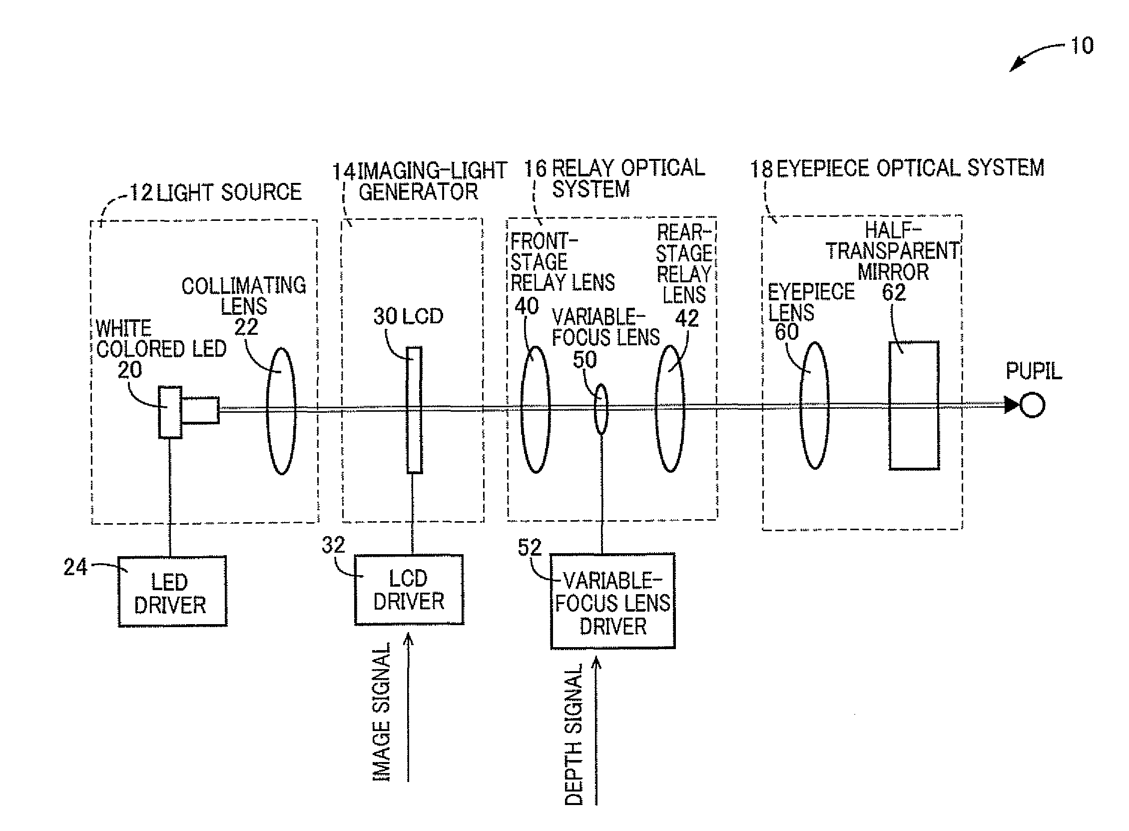
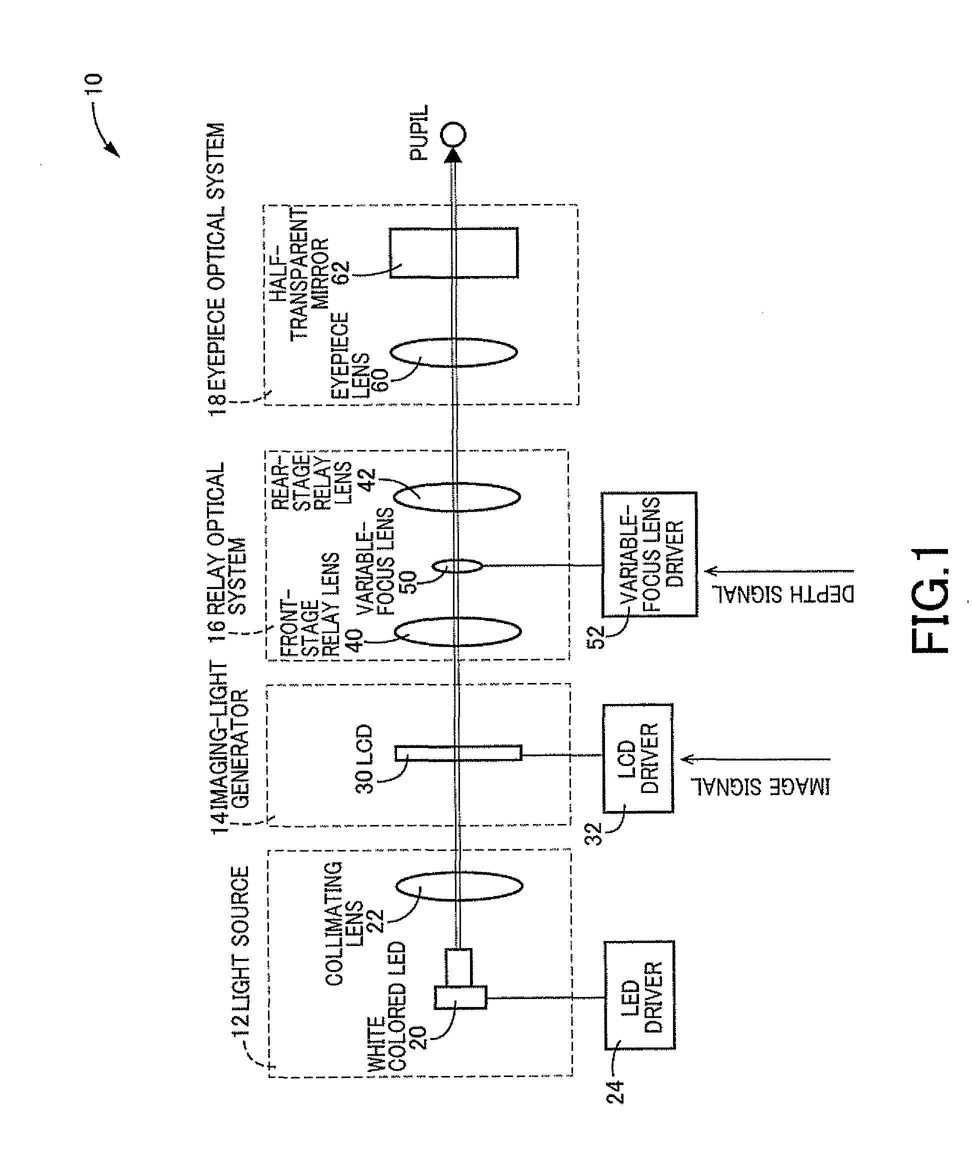
[0071]Referring now to FIG. 1, there is illustrated conceptually a head-mounted display device 10 according to an illustrative first embodiment of the invention. This head-mounted display device 10 is an image display device which is mounted on a viewer's head (not shown) when in use.

[0072]The head-mounted display device 10 is generally configured to spatially modulate surface light emitted from a light source at a time, using a spatial light modulator, on a per-pixel basis, and project the thus-generated imaging light through the viewer's pupil, directly onto the viewer's retina, to thereby allow the viewer to view an image as a virtual image.

[0073]More specifically, the head-mounted display device 10 is configured to include a light source 12; an imaging-light generator 14; a relay optical system 16; and an eyepiece optical system 18, in a linear array, in the description order.

[0074]The light source 12 is configured to include a white colored LED (Light-Emitting Diode) 20 acting ...

second embodiment

[0123]The calibration mechanism 120, which is common in structure to the wavefront-curvature offset mechanism 100 in the second embodiment, is configured to include the operated portion 104; the stationary portion 106; the linearly movable portion 108; the rotary portion 110; and the motion converting mechanism 112. The variable-focus lens 50 is securely fixed to the linearly movable portion 108.

[0124]The calibration mechanism 120 allows the user to displace the variable-focus lens 50 from its default position (i.e., its initial position), in a desired direction by a desired length. This allows the user to adjust the position of the variable-focus lens 50 so that the user can view a display image sharply, while viewing the display image, to thereby offset the wavefront curvature of the imaging light from the default value by a desired amount.

[0125]Next, an illustrative fourth embodiment of the invention will be described below. The present embodiment is common to the first embodimen...


PUM


Abstract

An image display device for optically displaying an image is disclosed. This device includes: a light source; an imaging-light generator converting light emitted from the light source, into imaging light representative of the image to be displayed, to thereby generate the imaging light; a relay optical system focusing the imaging light emitted from the imaging-light generator, on an image plane which is located at an optically conjugate position to the imaging-light generator, the relay optical system defining a pupil through which the imaging light passes, within the relay optical system; a variable-focus lens disposed at a position generally coincident with the pupil, the variable-focus lens having a varying focal length; and a wavefront-curvature adjuster configured to vary the focal length by operating the variable-focus lens, to thereby adjust a wavefront curvature of the imaging light emitted from the relay optical system.

Description

CROSS-REFERENCE TO RELATED APPLICATIONS[0001]The present application is based on and claims the benefit of priority from Japanese Patent Application No. 2008-017043 filed Jan. 29, 2008, and International Application No. PCT / JP2009 / 051044 filed Jan. 23, 2009, the contents of which are incorporated herein by reference in their entirety.[0002]This application is a continuation-in-part application of International Application No. PCT / JP2009 / 051044 filed Jan. 23, 2009, now pending, which was published in Japanese under PCT Article 21(2).BACKGROUND OF THE INVENTION[0003]1. Field of the Invention[0004]The invention relates generally to techniques of optically displaying an image, and more particularly to improvements in techniques of adjusting a wavefront curvature of imaging light representing an image to be displayed.[0005]2. Description of the Related Art[0006]As techniques of optically displaying an image, there are known, for example, a technique of projecting imaging light representi...

Claims


Application Information

Patent Timeline
IPC IPC(8): H04N3/26G03B21/14G02B15/14
CPCG02B3/12G02B15/00G02B2027/0127G02B27/0172G02B27/017
Inventor WATANABE, MITSUYOSHI
Owner BROTHER KOGYO KK
Why Eureka
Try Eureka