Radiographic apparatus and imaging method thereof

a radiographic apparatus and imaging method technology, applied in electrical apparatus, medical science, diagnostics, etc., can solve the problems of not being able to image the entire area, generating twice the labor of the operator to perform imaging, and not being able to complete imaging, so as to avoid the effect of generating twice the labor of the operator

Inactive Publication Date: 2010-11-18
CANON KK
View PDF3 Cites 15 Cited by
  • Summary
  • Abstract
  • Description
  • Claims
  • Application Information

AI Technical Summary

Benefits of technology

[0013]The present invention enables the operator to designate whether or not to continue imaging if divided capture has been interrupted. Accordingly, it is possible to avoid generating twice the labor for the operator, and also prevent an object from undergoing unnecessary exposure to radiation.

Problems solved by technology

In such cases, it is not possible to image the entire area by a single imaging process, so imaging is performed in a plurality of divided imaging processes.
However, when divided images are obtained in the above-described manner, there have been situations where imaging cannot be completed normally up to the third image if the object moves during imaging, or if the operator releases the irradiation switch.
Accordingly, it has cost twice the labor for the operator to perform imaging again from the first image, and this has also caused an object to undergo unnecessary exposure to radiation.

Method used


Image

  • Radiographic apparatus and imaging method thereof
  • Radiographic apparatus and imaging method thereof
  • Radiographic apparatus and imaging method thereof

Examples


embodiment 1

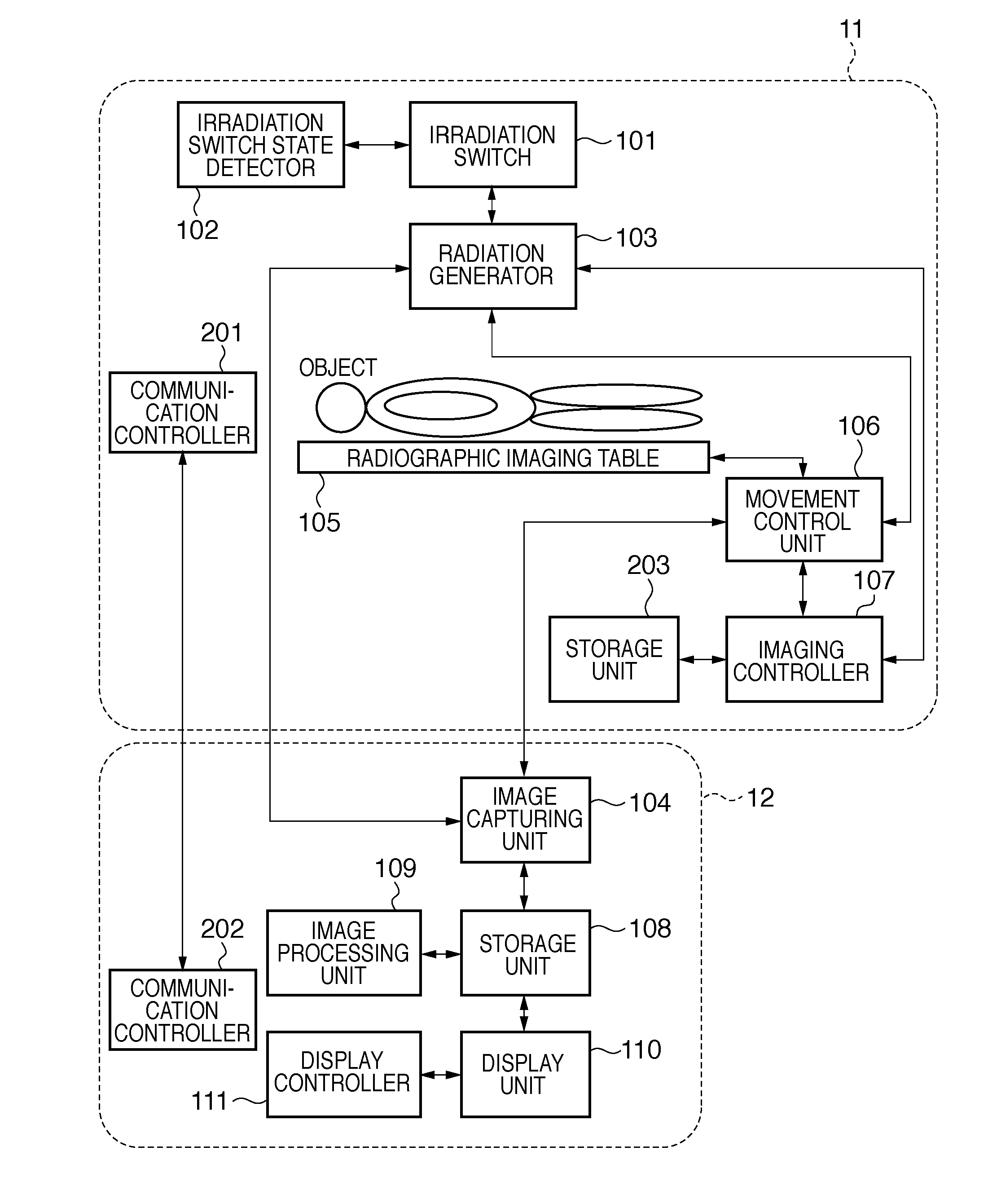
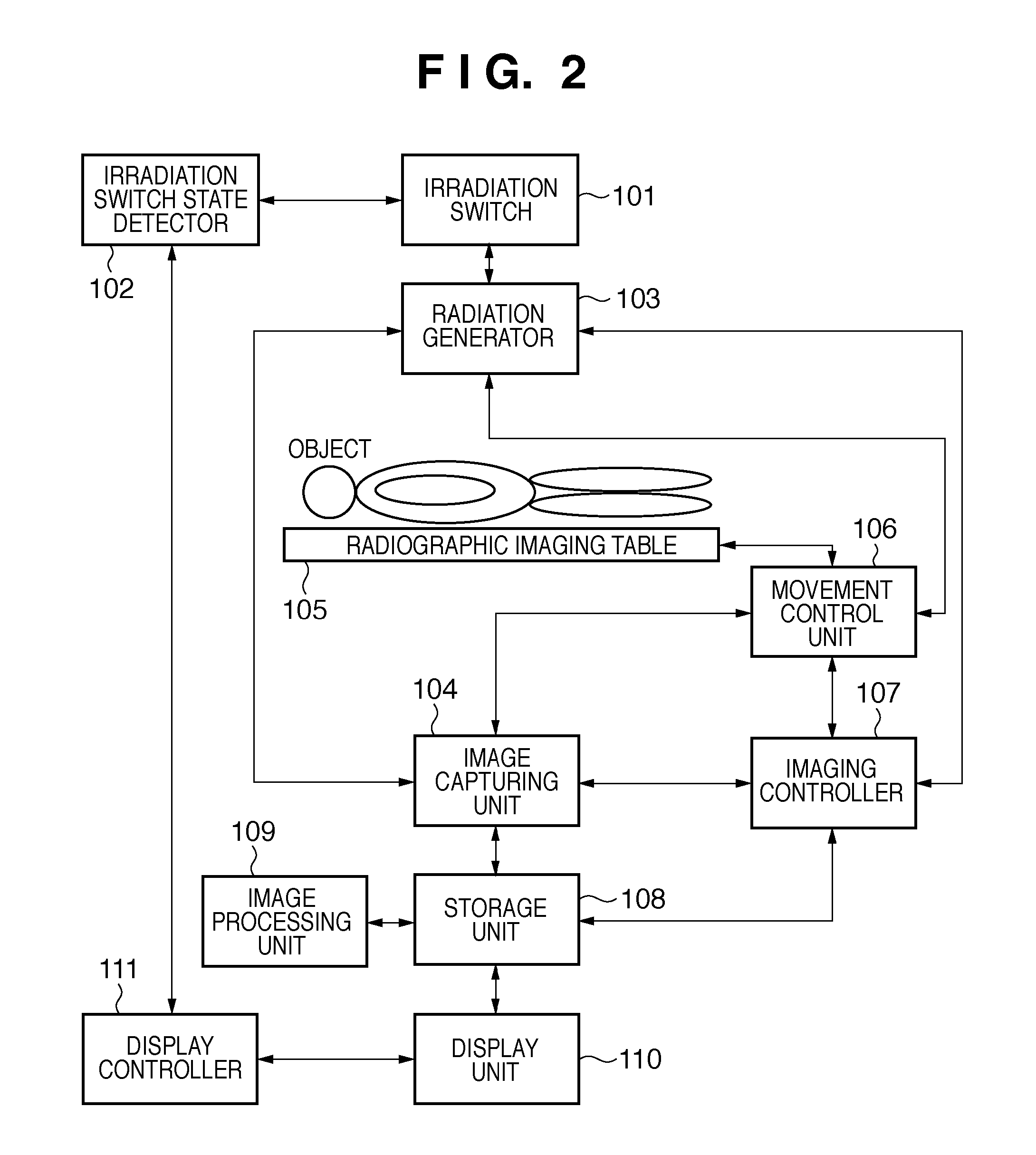
[0045]In Embodiment 1, a description will be given of a divided capture method in the configuration shown in FIG. 2.

[0046]FIGS. 5A and 5B are flowcharts illustrating a flow of a divided capture method of the present invention in the configuration shown in FIG. 2.

[0047]FIG. 6 is a diagram illustrating a radiation irradiation region.

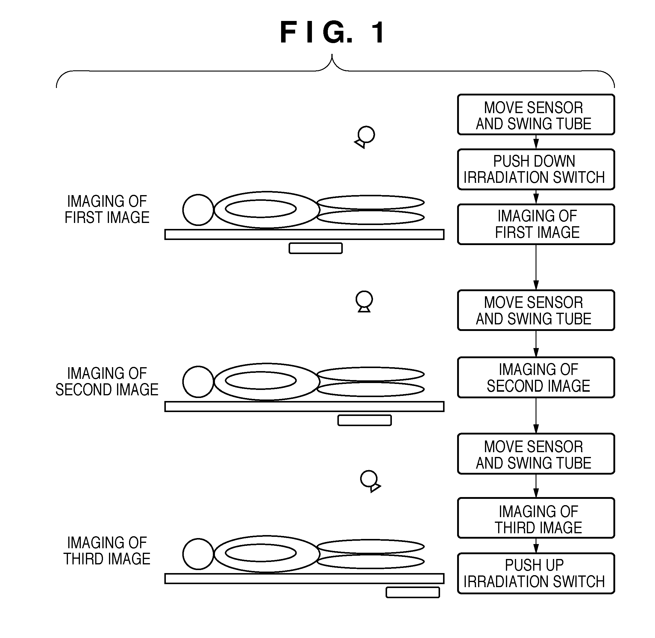
[0048]First, in step S1, placement conditions including a radiation irradiation region for an object and the rotation angle of an imaging sensor with respect to the axis of the object, and a plurality of body parts divided for the object are determined in accordance with a designation from the operator.

[0049]Here, the imaging sensor serving as the image capturing means will be described.

[0050]FIG. 6 is a diagram illustrating a radiation irradiation region. As shown in FIG. 6, a radiation irradiation region 602 is located at the central portion of an imaging sensor 601. When radiography is performed, an actual irradiation region is narrowed by a device call...

embodiment 2

[0074]In Embodiment 2, an example will be described in which the number of times imaging implementation information indicating implementation of each imaging process has been acquired is used as a condition for determining whether or not all the imaging processes have been completed, unlike Embodiment 1 in which the index of the number of captured images is used as a condition for determining whether or not all the imaging processes have been completed.

[0075]FIGS. 9A and 9B are flowcharts illustrating a flow of a divided capture method of the present invention in Embodiment 2. In FIGS. 9A and 9B, the details of the steps other than steps S101 to S104 are the same as those of the steps described in relation to FIGS. 5A and 5B, so the description thereof has been omitted here.

[0076]In step S101, the count value (Count) indicating the number of times the imaging implementation information has been acquired is initialized to “1”.

[0077]In step S102, the imaging controller 107 compares th...

embodiment 3

[0080]In Embodiment 3, a description will be given of a divided capture method that takes into account the case where the object has moved during imaging in the configuration shown in FIG. 2.

[0081]FIGS. 10A and 10B are flowcharts illustrating a flow of a divided capture method of the present invention in Embodiment 3. In FIGS. 10A and 10B, the details of the steps other than S201 are the same as those of the steps described in relation to FIGS. 5A and 5B, so the description thereof has been omitted here.

[0082]In step S201, the image processing unit 109 determines whether or not composition processing can be performed for each imaging process. That is, if the object has moved during imaging an image, the image cannot be successfully composed during the later composition processing; accordingly, in Embodiment 3, each of the plurality of divided images is composed for each imaging process, the degree of matching between the divided images is calculated, and whether or not the degree of...


PUM


Abstract

There is provided a technology that enables an operator to designate whether or not to continue imaging if divided capture has been interrupted in a radiographic apparatus. During continuation of divided capture, the state of an irradiation switch for designating irradiation of radiation is detected by an irradiation switch state detection unit. When a suspension of the designation of irradiation of radiation has been detected, information indicating continuation of imaging, performing of imaging again, or cancellation of imaging is presented to an operator, thereby preventing an unintended interruption of imaging.

Description

BACKGROUND OF THE INVENTION[0001]1. Field of the Invention[0002]The present invention relates to a radiographic apparatus and a radiographic method for obtaining a radiation image of an object by irradiation of radiation, and particularly relates to a technology for a method in which the same object is imaged in a plurality of imaging processes.[0003]2. Description of the Related Art[0004]Conventionally, imaging using radiation has been used in various fields, and particularly in the medical field, is one of the most important methods for diagnosis. In recent years, an imaging sensor that collects, as digitized image data, a radiation image obtained by radiography has also been put into practical use, and digitization is underway in the radiography field. In general, the larger type of such imaging sensors predominantly has a size of about 43 cm×43 cm.[0005]When radiography is performed using such an imaging sensor, there are cases where an area larger than the imaging sensor (for e...

Claims


Application Information

Patent Timeline
Patent Type & Authority Applications(United States)
IPC IPC(8): H05G1/56
CPCA61B6/00A61B6/542A61B6/469
Inventor YAMADA, NAOKI
Owner CANON KK
Why Eureka
Try Eureka