Double-speed automatic degreasing centrifuge

A degreasing and centrifuge technology, applied in the field of two-speed automatic degreasing centrifuges, can solve the problems of decreased oil rejection, difficult manufacturing, unsuitable for large-scale, automated assembly line operations, etc., and achieves reasonable structure and overall effect. Good results

Inactive Publication Date: 2010-02-24
蔡体勇
View PDF1 Cites 8 Cited by
  • Summary
  • Abstract
  • Description
  • Claims
  • Application Information

AI Technical Summary

Problems solved by technology

This design can realize the shaking and separation of the oil attached to the received product, but when the oil is separated, it is structurally in the same cavity as the product shaking barrel, and it is easy to cause the reflux of the thrown oil during the shaking process, and When the product is exported out, it must also rely on the conical cover and the cover lifter. This is a static product lifting process. Therefore, when the rotation is stopped, the repeated pollution of the dried product due to the return of the thrown oil, Its oil throwing effect is reduced; the upper part of the design has a cover, and the filling hopper must be used for feeding. First, the entire design structure is increased, and manufacturing becomes more difficult. Second, it is not suitable for one-time input of large quantities of parts; this design The outer closed barrel is a straight-through structure, and only one batch of products can be made during processing. When the products are continuously input, the original products will be polluted by the products that enter later, which limits the processing capacity of the products. It is not suitable for large batches, Automated Pipeline Operation

Method used


Image

  • Double-speed automatic degreasing centrifuge
  • Double-speed automatic degreasing centrifuge
  • Double-speed automatic degreasing centrifuge

Examples


Embodiment Construction

[0018] The present invention will be further described in detail below in conjunction with the accompanying drawings and embodiments.

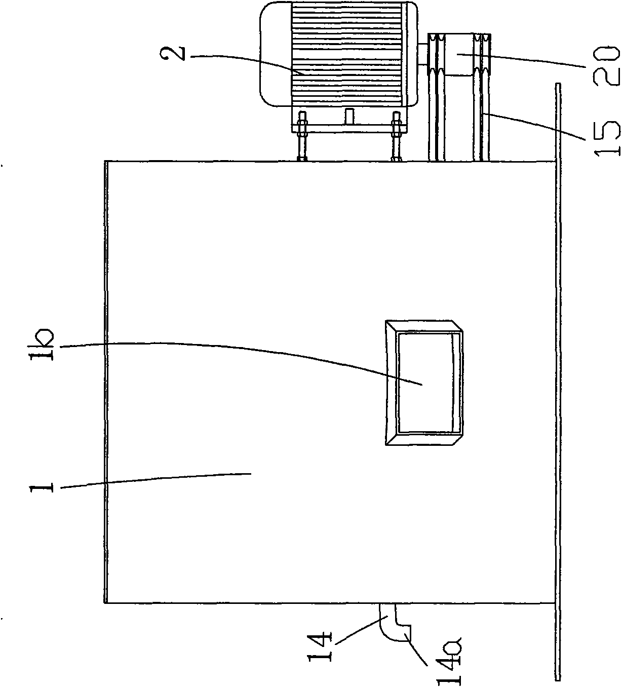
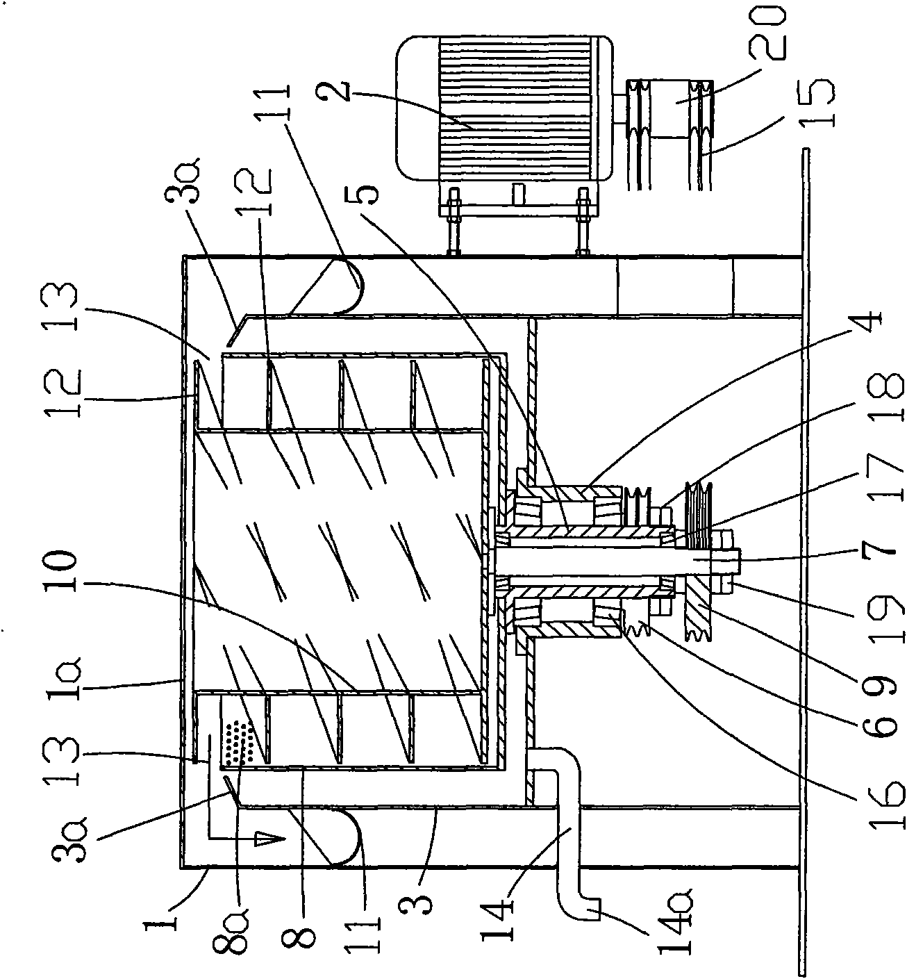
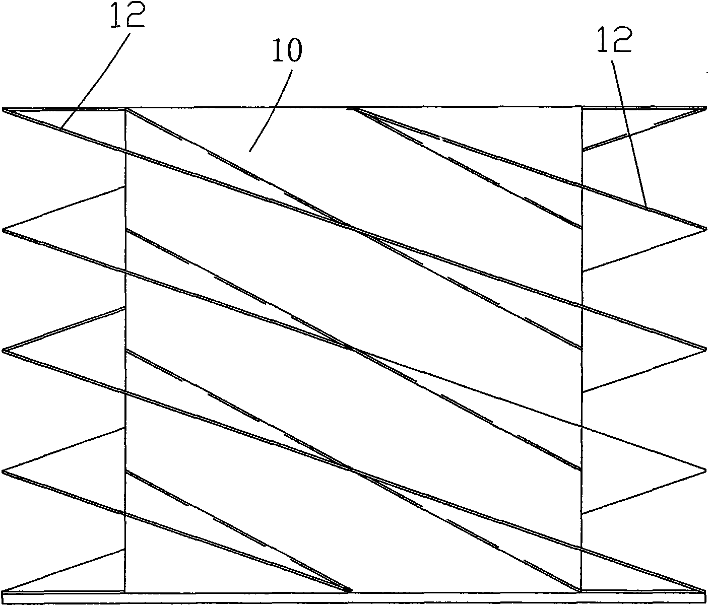
[0019] Such as Figure 1 to Figure 4 As shown, the description of the icon numbers is as follows: body casing 1, feeding port 1a, discharging port 1b, motor 2, oil tank 3, inclined ring edge 3a, outer bearing sleeve 4, centrifugal shaft 5, centrifugal shaft pulley 6, lifting shaft 7. Isolation barrel 8, mesh 8a, lifting shaft pulley 9, lifting frame 10, discharge channel 11, lifting plate 12, gap 13, oil outlet pipe 14, oil outlet 14a, belt 15, centrifugal rotor 16, lifting rotation Body 17, centrifugal tightening nut 18, lifting and tightening nut 19, motor pulley disc 20.

[0020] In the embodiment of the present invention, a double-speed automatic degreasing centrifuge includes a body casing 1 of a hollow structure, a motor 2 is fixed on the outer wall of the body casing 1, and an oil tank 3 is embedded and fixed in the inner cavity of the...


PUM


Abstract

The invention relates to a double-speed automatic degreasing centrifuge which comprises a hollow centrifuge jacket, wherein a motor is fixed on the outer wall surface of the centrifuge jacket; an oilcontaining bucket is embedded and fixed in an inner cavity of the centrifuge jacket; the top end of a lifting shaft is provided with a lifting rack which can receive a product, and the lifting rack isembedded in and matched with an inner middle cavity of an isolating bucket; a material outlet channel is arranged between the outer wall surface of the oil containing bucket and the inner wall surface of the centrifuge jacket; the circumference of the lifting rack is provided with a lifting plate with a helical structure; the peripheral wall of the isolating bucket is uniformly provided with netholes, and oil liquid generated by the centrifugal rotation of a product is directly thrown into an inner cavity on the upper part of the oil containing bucket through the net holes. The lifting platewith a high-end configuration is adopted, thereby realizing the automatic separation during the lifting of the product. The lifting rack is provided with the lifting plate with the helical structure,thus the product can be easily lifted, and the integral effect is excellent. The lifting rack and the isolating bucket are simultaneously operated at double speed, thus, while the product is thrown to clear greasy dirt, the thrown greasy dirt can be drained outwards, furthermore, the problem of high labor intensity is saved and the mechanized operation degree is improved.

Description

technical field [0001] The invention relates to the technical field of centrifugal machines, in particular to a two-speed automatic degreasing centrifuge. Background technique [0002] At present, the structure of centrifugal equipment in the society tends to be diversified, and its scope of use is also wider and wider, including the separation of heavy metals contained in oil stains, the drying of oily dirt attached to general products, etc.; When the drying effect of greasy dirt is used, its prior art, as the patent No. is ZL200620018197.2 Chinese patent literature " automatic centrifuge " (announcement number is CN2892280Y) is exactly this type of design; It is composed of drum, drum shaft, conical cover, cover lifter, drum shaft anti-swing device and stuffing hopper. This design can realize the shaking and separation of the oil attached to the received product, but when the oil is separated, it is structurally in the same cavity as the product shaking barrel, and it is ...

Claims


Application Information

Patent Timeline
Patent Type & Authority Applications(China)
IPC IPC(8): B04B3/04B04B7/18B04B7/04B04B9/02B04B9/08
Inventor 蔡体勇陆昱森
Owner 蔡体勇
Why Eureka
Try Eureka