Dust collector structure

A technology for vacuum cleaners and dust cups, which is applied to the installation of vacuum cleaners, suction filters, and electrical equipment. It can solve the problems of high cost and difficulty in disassembling and separating dust cup components and motor components, and achieves the effect of easy disassembly.

Pending Publication Date: 2021-02-12
NINGBO FUJIA IND
View PDF0 Cites 0 Cited by
  • Summary
  • Abstract
  • Description
  • Claims
  • Application Information

AI Technical Summary

Problems solved by technology

During the working process of the vacuum cleaner, the dust cup assembly and the motor assembly must always be connected and achieve a sealed effect at the connection, so the magnetic attraction force between the magnetic attraction components must be large, and the magnetic attraction force will be large. It is not easy to disassemble and separate the dust cup assembly and the motor assembly. Users often have to spend a lot of effort to overcome the magnetic force of the magnetic attraction assembly and separate the dust cup assembly from the motor assembly.

Method used


Image

  • Dust collector structure
  • Dust collector structure
  • Dust collector structure

Examples


Embodiment 1

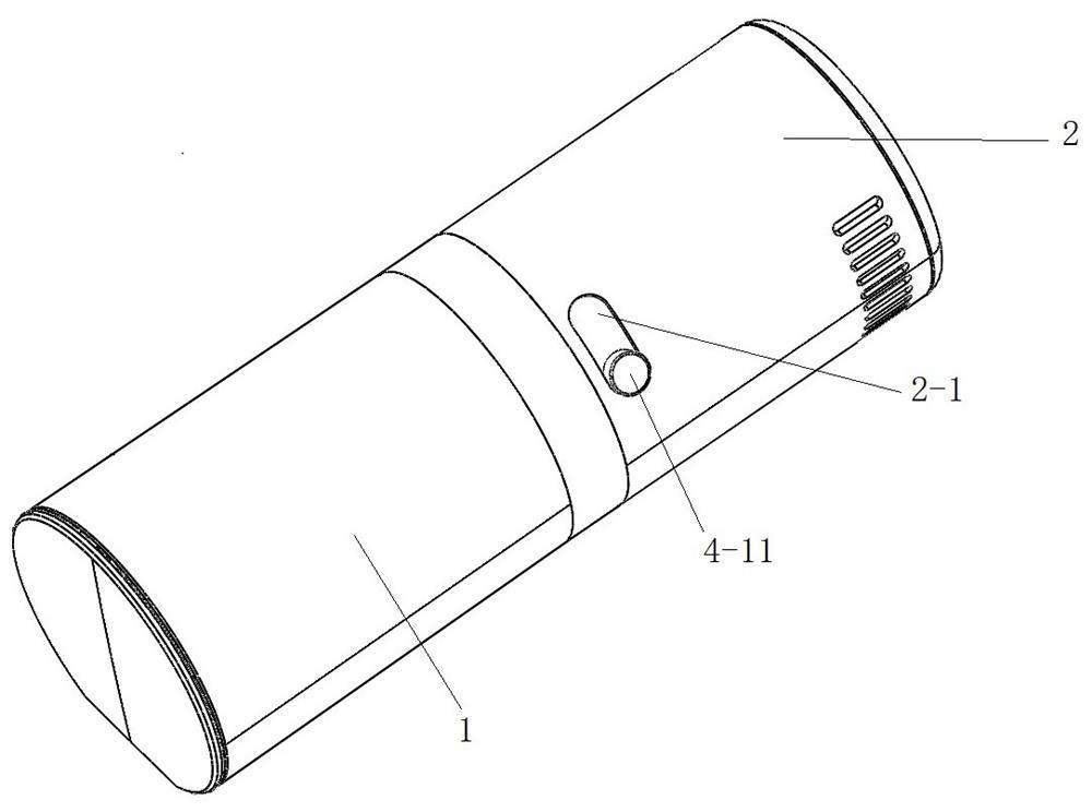
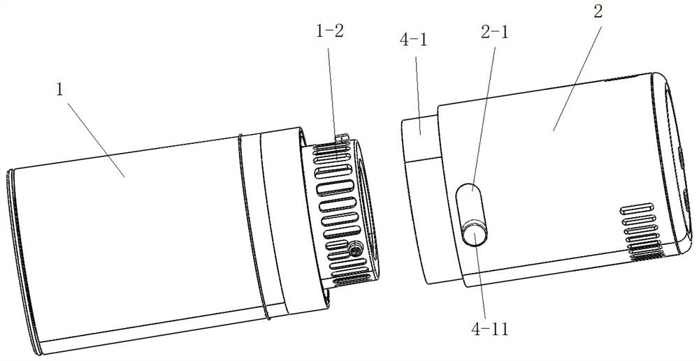
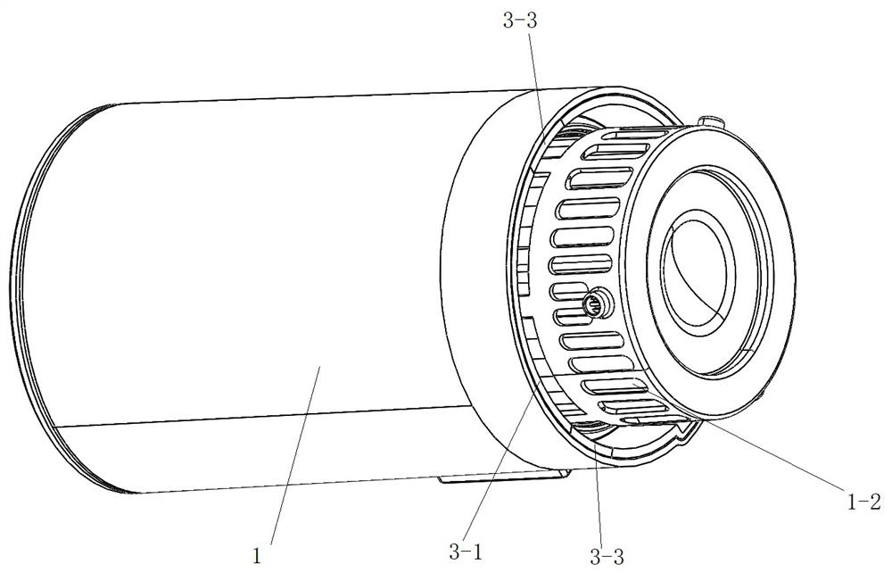
[0028] Such as Figure 1 to Figure 4As shown in , the structure of the vacuum cleaner of the present invention includes a dust cup assembly 1 and a motor assembly 2, on which a filter element 1-2 is installed, and the dust cup assembly 1 and the motor assembly 2 are magnetically connected by a magnetic attraction assembly 3. The magnetic attraction assembly 3 includes a first magnet mounting base 3-1, a second magnet mounting base 3-2 and several magnetic blocks 3 respectively mounted on the first magnet mounting base 3-1 and the second magnet mounting base 3-2 -3; the first magnet mounting base 3-1 is installed on the opening end of the dust cup assembly housing, and several magnetic blocks 3-3 are evenly fixed on the first magnet mounting base 3-1; the second magnet mounting base 3-2 Installed on the open end of the motor assembly housing, several magnetic blocks 3-3 are uniformly fixed on the second magnet mounting base 3-2; the magnetic block on the first magnet mounting b...

Embodiment 2

[0033] The differences between this embodiment and the vacuum cleaner structure in Embodiment 1 are as Figure 6 As shown, several mutually attracting magnetic blocks 3-31 and several mutually repelling magnetic blocks 3-32 are evenly installed on the rotating wall 4-2. The phase-attracting magnetic blocks 3-31 are engaged with the magnetic blocks 3-3 on the first magnet mounting base 3-1 in one-to-one correspondence, so that the dust cup assembly 1 and the motor assembly 2 are magnetically connected. Toggle the dial 4-11, and the dial 4-11 drives the rotatable wall 4-2 to rotate on the outer wall of the fixed wall 4-1, so that the phase-attracting magnetic block 3-31 can be connected with the first magnet mounting seat 3-1 The magnetic blocks 3-3 on the top are misaligned with each other, and at the same time, the magnetic blocks 3-32 and the magnetic blocks 3-3 on the first magnet mounting base 3-1 are mutually repelled one by one, so that the dust cup assembly 1 and the mot...

Embodiment 3

[0035] The difference between this embodiment and the structure of the vacuum cleaner in Embodiment 1 is that the rotating assembly 4 is arranged on the first magnet mount 3-1, and the fixed wall 4-1 is installed on the inner wall of the opening end of the dust cup assembly housing. The button chute 2-1 is arranged on the housing of the dust cup assembly.


PUM


Abstract

The invention provides a dust collector structure, which comprises a dust cup assembly, a motor assembly and a magnetic attraction assembly, wherein the magnetic attraction assembly comprises magneticblocks installed on the dust cup assembly and the motor assembly respectively, and the dust cup assembly and the motor assembly are connected together through corresponding magnetic attraction of themagnetic blocks; the dust cup assembly and the motor assembly can rotate relative to each other, so that the magnetic blocks installed on the dust cup assembly and the magnetic blocks installed on the motor assembly are staggered; or a rotating assembly is arranged, and the rotating assembly can enable the magnetic blocks arranged on the dust cup assembly and the magnetic blocks arranged on the motor assembly to be mutually staggered. According to the dust collector structure, no matter how large the magnetic attraction acting force between the magnetic blocks in the magnetic attraction assembly is, only the magnetic blocks arranged on the dust cup assembly and the magnetic blocks arranged on the motor assembly need to be staggered, so that the magnetic attraction force between the magnetic blocks on the dust cup assembly and the magnetic blocks on the motor assembly is reduced, and the dust cup assembly and the motor assembly are easy to detach.

Description

technical field [0001] The present invention relates to the technical field of vacuum cleaners, more specifically to a structure of vacuum cleaners. Background technique [0002] Vacuum cleaner is a widely used household cleaning product. Its working principle is to use the motor to drive the blades to rotate at high speed, generate air negative pressure in the sealed casing, and absorb dust. The dust is sucked into the air duct with the air, and passes through the air-solid After the separation and filter element filters the solid particle impurities, the dust is collected into the dust cup, and the relatively clean air is discharged out of the vacuum cleaner shell. For some small vacuum cleaners, the dust cup is small and easy to fill up. After use, it is often necessary to remove the dust cup and filter element for cleaning. In the existing vacuum cleaner products, in order to facilitate the disassembly and assembly of the dust cup and the filter element, the filter elem...

Claims


Application Information

Patent Timeline
Patent Type & Authority Applications(China)
IPC IPC(8): A47L9/10A47L9/28A47L9/00
CPCA47L9/00A47L9/10A47L9/106A47L9/28
Inventor 方剑强郑建民赵烨健
Owner NINGBO FUJIA IND
Why Eureka
Try Eureka