Adaptive device for shifting imaging axis across fiber-optic endfaces in multi-fiber connector for inspection

a multi-fiber connector and adaptive device technology, applied in the direction of microscopes, optics, instruments, etc., can solve the problems of signal loss, imaging axis cannot be aligned with and focused on the center of every endface,

Active Publication Date: 2010-11-18
LIGHTEL TECH
View PDF4 Cites 12 Cited by
  • Summary
  • Abstract
  • Description
  • Claims
  • Application Information

AI Technical Summary

Problems solved by technology

This creates an urgent need for regularly inspecting and maintaining the multi-fiber connectors in place, which are often situated behind backplanes or in locations which are very difficult to access.
It is well known in the fiber-optic communication industry that the endfaces of optical fibers within communication systems must be kept clean and undamaged, otherwise serious signal loss could result.
However, with this device, the imaging axis of the microscope moves along a circular track relative to the fitting tip and as a result the imaging axis cannot be aligned with and focused on the center of every endface in a multi-fiber connector—since the endfaces in a multi-fiber connector are almost always arranged in a straight line.

Method used


Image

  • Adaptive device for shifting imaging axis across fiber-optic endfaces in multi-fiber connector for inspection
  • Adaptive device for shifting imaging axis across fiber-optic endfaces in multi-fiber connector for inspection
  • Adaptive device for shifting imaging axis across fiber-optic endfaces in multi-fiber connector for inspection

Examples


Embodiment Construction

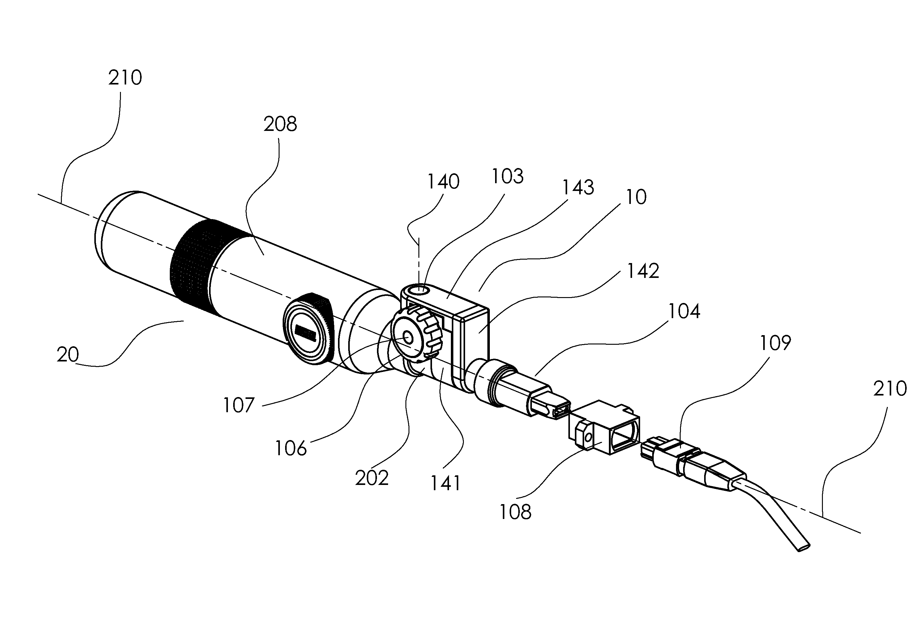
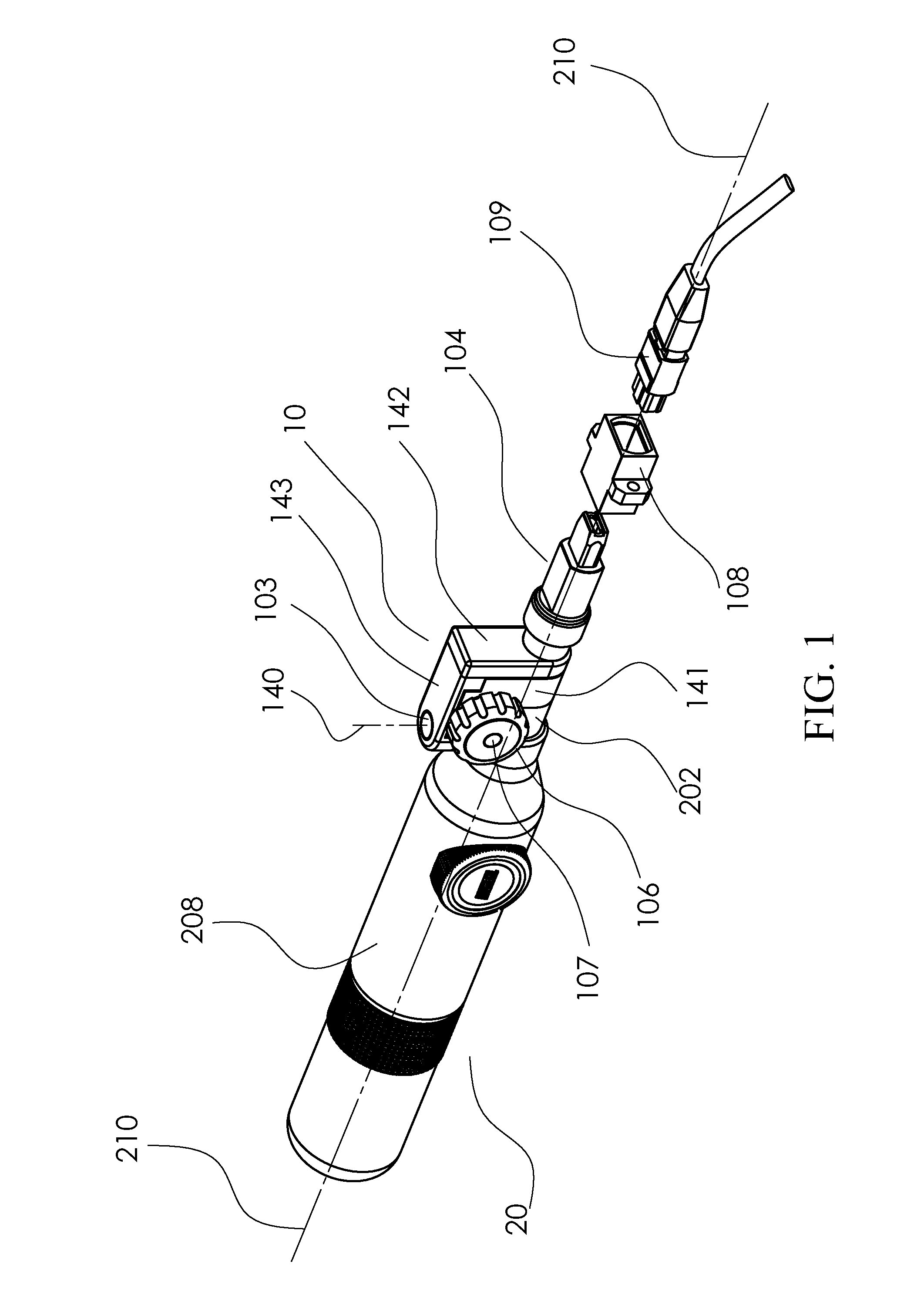
[0022]FIG. 1 illustrates the adaptive device 10 for shifting the imaging axis of a microscope across the fiber-optic endfaces of a multi-fiber connector for inspecting the fiber-optic endfaces according to a preferred embodiment of the present invention. In FIG. 1, the adaptive device 10 is shown together with a handheld microscope 20, a multi-fiber connector 109 and a connector adaptor 108. The microscope 20 has a microscope body 208 and an optical tube 202 at the front end of the microscope body 208. In addition, the imaging axis 210 of the microscope 20, which passes through the center of the field of view of the microscope 20, is also shown in FIG. 1.

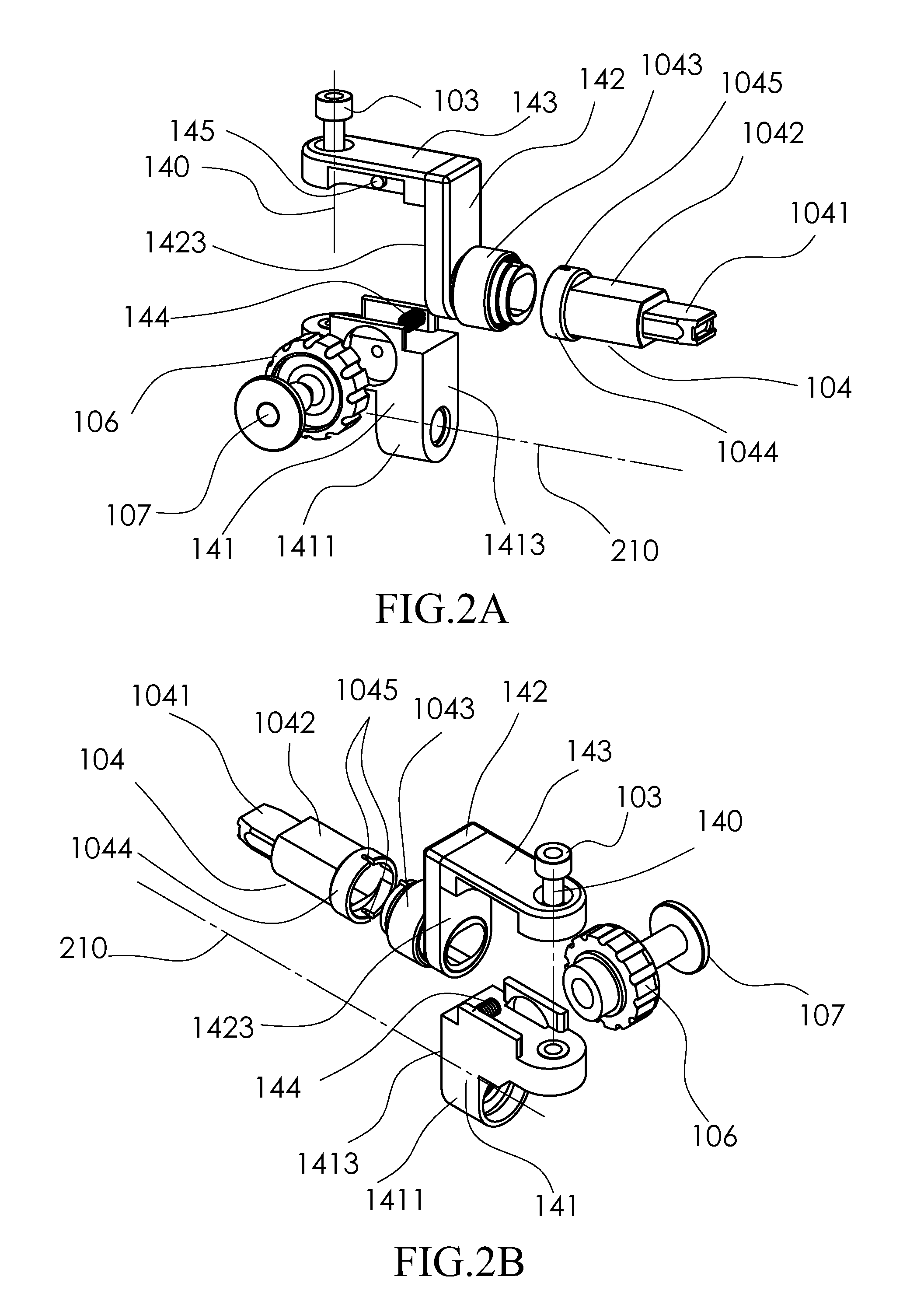
[0023]FIG. 2A and FIG. 2B show two exploded views of the adaptive device 10 in FIG. 1. FIG. 3A and FIG. 3B show a perspective view and a top plan view, respectively, of the assembled adaptive device 10 with a top section of the swinging lever 143 removed to illustrate the interaction among its internal components. As illustrated in ...


PUM


Abstract

A device for shifting the imaging axis of a microscope across the endfaces of a multi-fiber connector for inspecting the endfaces comprises: a supporting body attached to the optical tube of a microscope and having an extended portion; a swinging lever mounted at one end to the extended portion of the supporting body and rotatable on an axis perpendicular to the imaging axis of the microscope; a connection piece connecting between the swinging lever and a fitting tip; a bevel wheel fastened to the supporting body; and a torsion spring for pushing the swinging lever against a slanted surface of the bevel wheel. The bevel wheel is adapted to swing the swinging lever relative to the supporting body so that the imaging axis of the microscope is moved relative to the fitting tip to selectively align the imaging axis across the endfaces for inspection.

Description

BACKGROUND OF THE INVENTION[0001]1. Field of the Invention[0002]The invention relates to fiber-optic connector inspection microscopes and more particularly to an adaptive device for shifting the imaging axis of a microscope across the endfaces of a multi-fiber connector for inspecting the fiber-optic endfaces through the microscope.[0003]2. Description of the Related Art[0004]The widespread implementation of fiber-optic communications for high-density interconnections has driven more and more multi-fiber connectors to be adopted in the industry. This creates an urgent need for regularly inspecting and maintaining the multi-fiber connectors in place, which are often situated behind backplanes or in locations which are very difficult to access.[0005]It is well known in the fiber-optic communication industry that the endfaces of optical fibers within communication systems must be kept clean and undamaged, otherwise serious signal loss could result. The demand for cleanliness for fiber-...

Claims


Application Information

Patent Timeline
Patent Type & Authority Applications(United States)
IPC IPC(8): G02B6/36
CPCG02B6/3833G02B6/3885G02B6/385
Inventor ZHOU, GEHUANG, SHANGYUAN
Owner LIGHTEL TECH
Why Eureka
Try Eureka