Passive optical network system and operation method thereof

a network system and optical network technology, applied in the field of optical network systems, optical line terminals, optical network units, can solve the problems of cmos technology fabricated using power consumption of digital signal processing lsi, and power consumption of pon, so as to reduce the amount of power consumption

Inactive Publication Date: 2010-11-18
HITACHI LTD
View PDF7 Cites 20 Cited by
  • Summary
  • Abstract
  • Description
  • Claims
  • Application Information

AI Technical Summary

Benefits of technology

[0013]According to the present invention, in the PON whose configuration is that a plurality of signals having different downstream transfer rates can be operated in a manner of being made mixed to each other by the time-division multiplexing, it becomes possible to implement the passive optical network system which permits the waste of the power consumption to be reduced down to the smallest possible degree on the basis of the end-user traffics.

Problems solved by technology

Here, it has been known that, the higher the transfer rate of a signal in a PON becomes, the larger amount of power each optical module and LSI for implementing the signal transfer function of the PON comes to consume.
Also, the digital-signal processing LSI fabricated using the CMOS technology consumes a power which is substantially proportional to the square of the rate of operation clocks.
Namely, from now on as well, there will remain the tendency that, the higher the transfer rate becomes, the larger amount of power the PON comes to consume.
Nevertheless, each optical module and LSI, which constitutes the actual PONs, operates and consumes the power even during the time-zone during which no data is substantially transferred.
This fact has become a cause for the occurrence of a tremendous amount of waste of power.
Namely, even when the signal which is addressed to another slave station has reached the slave station, the components such as the optical modules continuously operate and consume the power.

Method used


Image

  • Passive optical network system and operation method thereof
  • Passive optical network system and operation method thereof
  • Passive optical network system and operation method thereof

Examples


Embodiment Construction

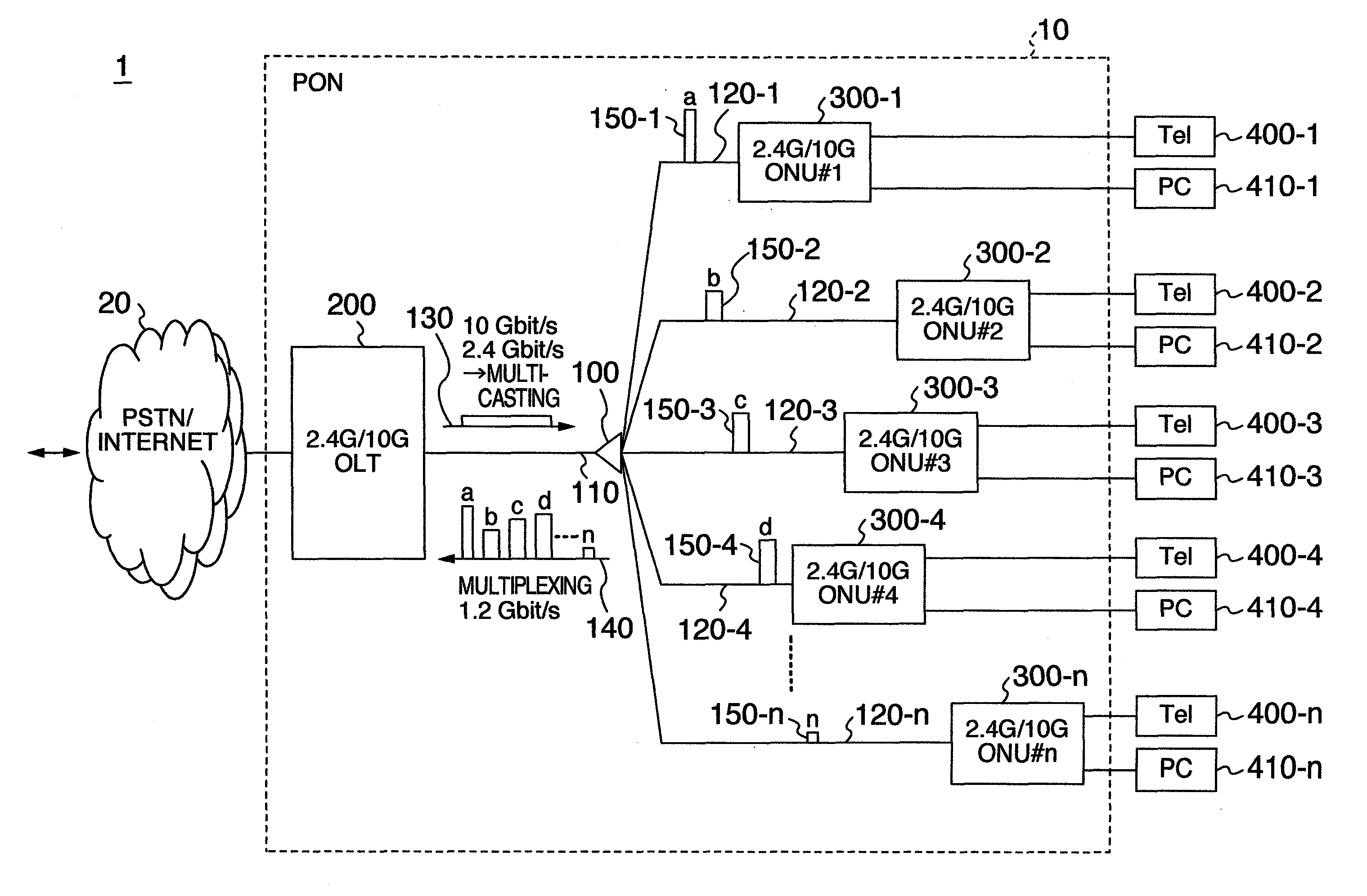
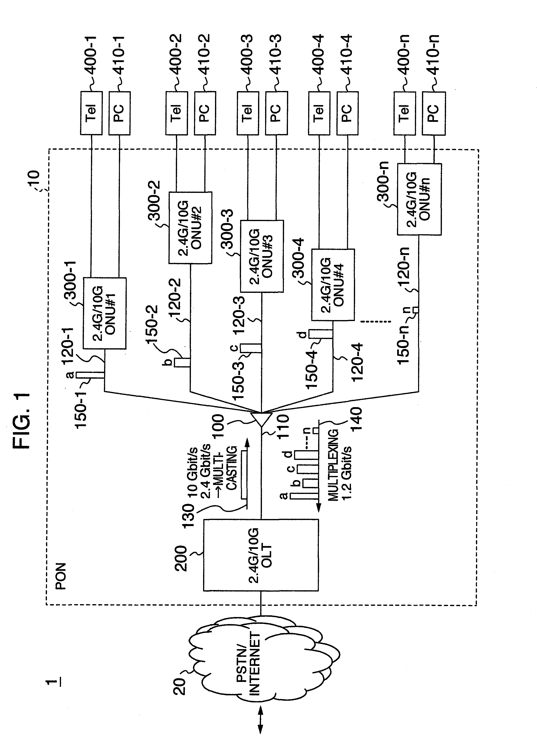
[0034]Hereinafter, referring to the drawings, the detailed explanation will be given below concerning the configuration and operation of a PON according to the present embodiment. At this time, the detailed explanation will be given selecting, as its example, the configuration and operation of a PON where the G-PON and the 10 G-PON are mixed. Here, the G-PON is defined by the ITU-T recommendation G. 984.3, and the 10 G-PON is a next-generation PON which is expected to be introduced in the near future, and whose transfer rate is raised.

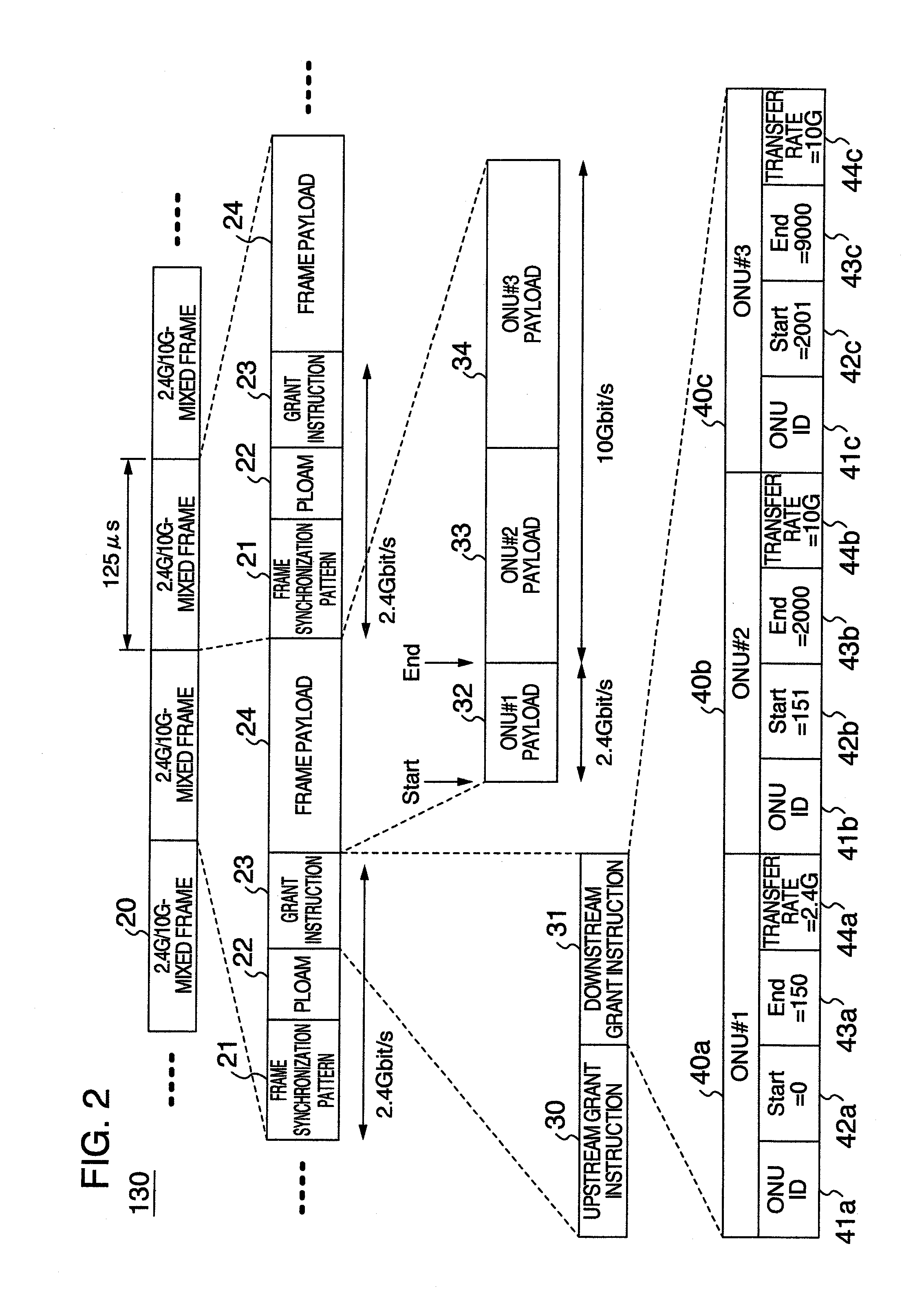
[0035]In the following explanation, the PON is assumed whose configuration is that variable-length data is processed using the TDM scheme in much the same way as in the G-PON. Moreover, in this example, the transfer rate of downstream data from the OLT to each ONU is of the mixed configuration of 10 Gbit / s (which is equal to 9.95328 Gbit / s accurately, but, hereinafter, will be referred to as “10 Gbit / s”) and 2.4 Gbit / s (which is equal to 2.48832 Gbit / s...


PUM


Abstract

A master station includes an optical transmission interface for transmitting signals to a plurality of slave stations at a first transfer rate or a second transfer rate which is higher than the first one, packet buffers for accumulating the signals addressed to each of the plurality of slave stations, and a control unit for determining transmission timings and transfer rates of the signals on the basis of an amount of the signals accumulated in the packet buffers, transmitting the signals with the determined timings and rates, and notifying each of the slave stations about the determined timings and rates. Each of the slave stations includes an optical reception interface for receiving the signals of the first transfer rate or the second transfer rate, and a control unit for controlling the optical reception interface on the basis of the timings and rates which the slave stations is notified.

Description

INCORPORATION BY REFERENCE[0001]The present application claims priority from Japanese application JP2009-116069 filed on May 13, 2009, the content of which is hereby incorporated by reference into this application.BACKGROUND OF THE INVENTION[0002]The present invention relates to a passive optical network system, an optical line terminal, and optical network units. More particularly, it relates to a passive optical network system in which a plurality of subscriber connection devices share an optical transmission line.[0003]In access communications networks whose subscribers are connected to each other, significant progress has been also made toward the high-rate / broad-band implementation of the communications networks. In accompaniment with this trend, there have been projects for the introduction of a Passive Optical Network system (which, hereinafter, will be referred to as “PON”). The PON is defined in such recommendations as the recommendation G. 984.3 made by the International T...

Claims


Application Information

Patent Timeline
Patent Type & Authority Applications(United States)
IPC IPC(8): H04J14/08H04L12/44
CPCH04Q11/0067H04Q2011/0064
Inventor KAZAWA, TOHRUSAKAMOTO, NORIHIROOHIRA, MASAKI
Owner HITACHI LTD
Why Eureka
Try Eureka