
Image forming apparatus and method of fixer temperature control in a power-saving mode

a technology of fixer and temperature control, which is applied in the field of image forming apparatus, can solve the problems of power consumption in the heater account, the temperature of the fixing part cannot be maintained at a printable temperature, and the wizard format settings have not yet been completed in some cases, so as to eliminate the waste of power and save power

Inactive Publication Date: 2015-01-13
KYOCERA DOCUMENT SOLUTIONS INC
View PDF8 Cites 6 Cited by
  • Summary
  • Abstract
  • Description
  • Claims
  • Application Information

AI Technical Summary

Benefits of technology

[0013]Thus, it is an object of the present invention to bring a time point at which making a setting in a wizard mode is completed closer to a time point at which warming up of a fixing part is completed to thereby eliminate waste of power at the fixing part and achieve power saving.
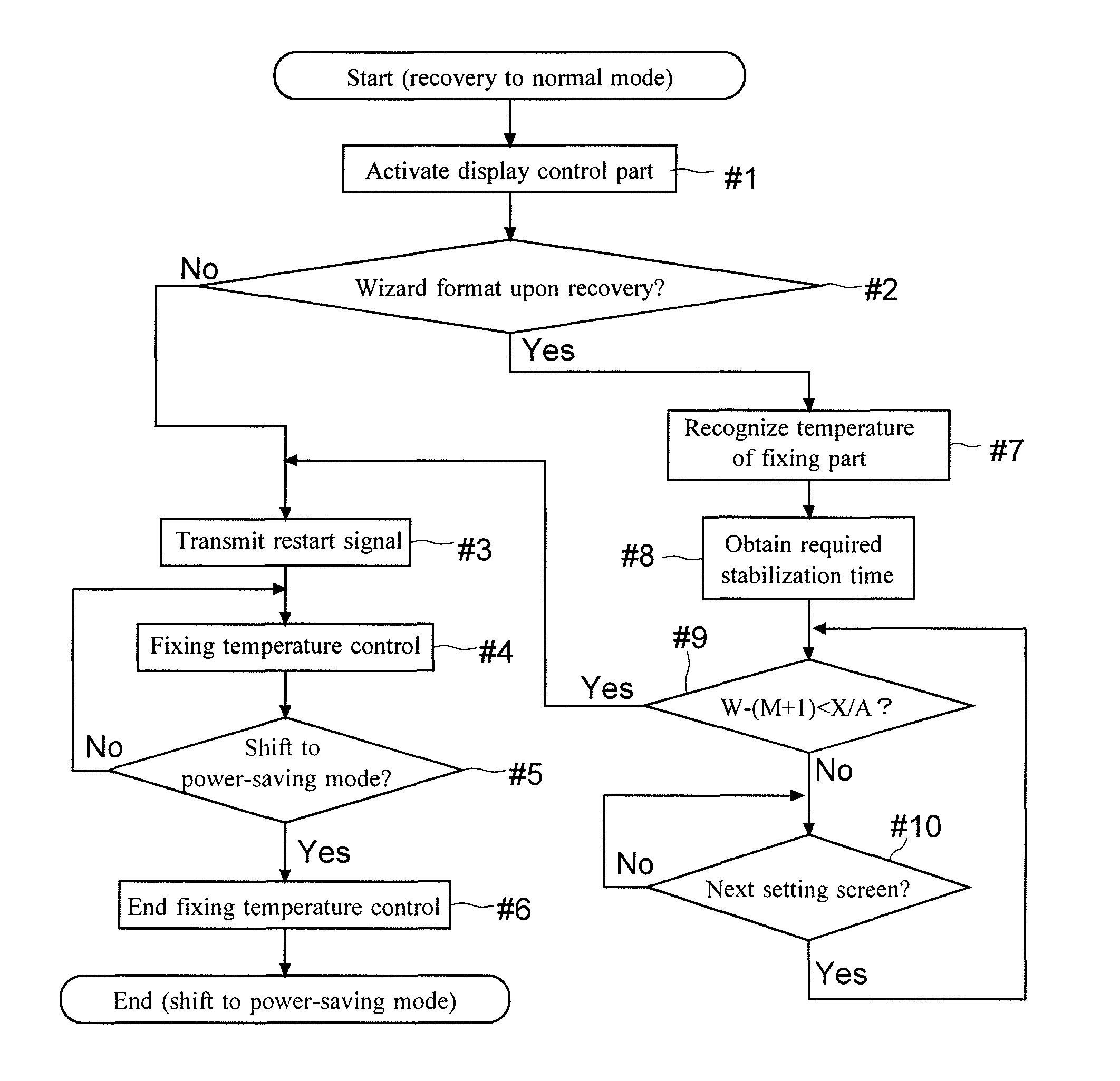
[0015]With this configuration, upon the recovery to the normal mode, a time point at which a job is started as a result of completion of making the settings in the wizard format can be brought closer to a time point at which the fixing part reaches the printable temperature. Therefore, waste of power consumed from when the fixing part is warmed up to the printable temperature to when the job is started following the completion of making the settings in the wizard format can be reduced.

Problems solved by technology

Typically, power consumption in the heater accounts for a large portion of power consumed in the image forming apparatus.
For example, when the power supply to the fixing part is stopped, a temperature of the fixing part cannot be maintained at a printable temperature.
Thus, even when warm-up has been started as a result of the recovery from the power-saving mode to the normal mode and then the fixing part has been warmed up to the printable temperature, making the settings in the wizard format have not yet been completed in some cases.
Therefore, there arises a problem of waste of power consumed at the fixing part from when the fixing part has been warmed up to the printable temperature to when a job starts in accordance with the settings made in the wizard format after the completion of making the settings.
Thus, the time required for the user to perform inputting in the wizard format may become longer.
The image forming apparatus described above does not accept the settings made in the wizard format.
Therefore, this image forming apparatus cannot cope with a problem of waste of power generated when the settings have been made in the wizard format, that is, the problem of the waste of the power consumed at the fixing part from when the fixing part is warmed up to the printable temperature to when a job starts following the completion of making the settings in the wizard format.

Method used


Image

  • Image forming apparatus and method of fixer temperature control in a power-saving mode
  • Image forming apparatus and method of fixer temperature control in a power-saving mode
  • Image forming apparatus and method of fixer temperature control in a power-saving mode

Examples


second embodiment

[0141]Next, based on FIGS. 11 and 12, one example of update of required stabilization time data in an MFP 100 according to a second embodiment of the invention will be described. FIG. 11 is a flow chart showing one example of a flow of update control of the required stabilization time data in the MFP 100 according to the second embodiment of the invention. FIG. 12 is an explanatory diagram showing one example of the update of the required stabilization time data in the MFP 100 according to the second embodiment of the invention.

[0142]Shown in the first embodiment is the example in which the required stabilization time data for obtaining the required stabilization time T1 from the start of the fixing temperature control to the warm-up to the printable temperature is fixed. However, the required stabilization time T1 depends on installation environment of the MFP 100. The required stabilization time T1 varies depending on inside and outside temperatures of the MFP 100 in particular in...

third embodiment

[0151]Next, based on FIGS. 13 to 15, a third embodiment of the invention will be described. FIG. 13A is an explanatory diagram showing one example of a login screen D2 of an MFP 100 according to the third embodiment of the invention, and FIG. 13B is an explanatory diagram showing one example of a soft keyboard screen D3. FIG. 14 is an explanatory diagram showing one example of a user registration change screen D4 of the MFP 100 according to the third embodiment of the invention. FIG. 15 shows one example of necessary time data according to the third embodiment of the invention.

[0152]In the first and second embodiments, upon the recovery from the power-saving mode, the timing of issuing the restart signal RS by the display control part 10 is defined based on, for example, the above (Formula 1). Then the fixed value is used for the necessary time T2 (A in the Formula 1) on one screen in the wizard format. In other words, without depending on the user, the necessary time T2 is defined ...


PUM


Abstract

Upon recovery from a power-saving mode to a normal mode and then restart of fixing temperature control from a state in which the fixing temperature control is stopped, a control part (display control part 10 obtains a current temperature of a fixing part based on output of a temperature detector and required stabilization time T1 based on required stabilization time data, and based on necessary time data A and the number of remaining setting screens on which settings need to be made in a wizard format, issues a restart signal RS for restarting the fixing temperature control between a first time point TP1 reached by tracing back by the required stabilization time T1 from a predicted time point at which making the settings is predicted to complete and a second time point TP2 as a time point the necessary time before the first time point.

Description

[0001]This application is based on Japanese Patent Application No. 2010-087981 filed on Apr. 6, 2010, the contents of which are hereby incorporated by reference.BACKGROUND OF THE INVENTION[0002]1. Field of the Invention[0003]The present invention relates to an image forming apparatus such as a copier, a multi-function printer (MFP), a printer, or a FAX machine.[0004]2. Description of Related Art[0005]In recent years, due to, for example, an increase in environmental problem consciousness, measures for reducing power consumption have been taken even for an image forming apparatus. For example, in an image forming apparatus forming a toner image, a fixing part including a heater is provided to heat and fix the toner image. Typically, power consumption in the heater accounts for a large portion of power consumed in the image forming apparatus. Thus, an image forming apparatus has been suggested which attempts to provide great power saving effect through power supply control at the fixi...

Claims


Application Information

Patent Timeline
Patent Type & Authority Patents(United States)
IPC IPC(8): G03G15/20G03G15/00H04N1/00
CPCG03G15/5004H04N1/00H04N1/00413H04N1/00435H04N1/00482H04N1/00896H04N1/00931G03G15/502G03G15/2078G03G15/5087G03G15/5091G03G15/2039H04N2201/0094G03G2215/00109
Inventor SAITO, YASUSHI
Owner KYOCERA DOCUMENT SOLUTIONS INC
Learn More