Corrugated paper forming machine with numerical motor speed control

a technology of numerical control and corrugated paper, which is applied in the field of corrugated paper forming machine with numerical control, can solve the problems of affecting the bonding effect between the rammed fluted paper and the face paper, the quality of the fluted paper is unstable, and the supply of paper material breaks or cracks, so as to avoid breakage or cracking of the supplied paper material, high level of ramming stability, and high level of product quality

Active Publication Date: 2016-11-15
LIN TZU CHE
View PDF8 Cites 0 Cited by
  • Summary
  • Abstract
  • Description
  • Claims
  • Application Information

AI Technical Summary

Benefits of technology

[0007]The present invention has been accomplished under the circumstances in view. It is therefore the main object of the present invention to provide a corrugated paper forming machine, which positively sucks up the supplied paper material by a suction force for accurately ramming into a fluted paper, avoiding breakage or cracking of the supplied paper material, and assuring a high level of ramming stability and integrity of the formation of the flute design on the paper material so that a high level of product quality and a high-yield production can be achieved.
[0008]To achieve this and other objects of the present invention, a corrugated paper forming machine of the invention comprises at least one ramming roller, motor operated suction device, a control module, and a sensor circuit. The at least one ramming roller is rotatable to ram a paper material into a fluted paper having flute design, each comprising a plurality of longitudinal teeth equiangularly spaced around the periphery thereof, a plurality of air suction grooves located in the periphery, a ventilation unit formed of a plurality of air outlets and located in one end thereof, and a plurality of air suction holes located in the air suction grooves in communication with the air outlets. The motor operated suction device comprises a suction motor connected with the ventilation unit and adapted for drawing air out of the at least one ramming roller to cause generation of a suction force in the air suction grooves. The control module is electrically coupled with the suction motor of the motor operated suction device. The sensor circuit is electrically coupled to the control module for sensing operation conditions of the paper material to be rammed by the ramming roller into a fluted paper, and providing detected numerical data to the control module to regulate the speed of the suction motor in changing the level of suction force. Thus, the suction force generated in the air suction grooves is optimally controlled, eliminating power waste and saving power cost.

Problems solved by technology

Further, the flexibility and shock absorbing functions of the wave-like structure of the internal lamination of corrugated paper are the unmatched features not found in other paper materials.
However, because the wheels and rollers of the corrugated paper forming machine are rotated at a speed as high as several meters per minute, a centrifugal force can be produced to bias the supplied paper material, leading to breakage or cracking of the supplied paper material, and affecting the effect of bonding between the rammed fluted paper and the face paper.
However, because a longitudinal gap exists between each two adjacent longitudinal teeth, the suction force thus created in unstable and cannot positively suck up the feeding paper material, leading to fluted paper quality instability and low yield rate.
This prior art design does not allow regulation of the suction force subject to change of paper operation conditions, and thus, the suction motor consumes a large amount of electrical power during its operation, leading to high power consumption cost and frequent maintenance shutdowns, and shortening the lifespan of the suction motor.

Method used


Image

  • Corrugated paper forming machine with numerical motor speed control
  • Corrugated paper forming machine with numerical motor speed control
  • Corrugated paper forming machine with numerical motor speed control

Examples


Embodiment Construction

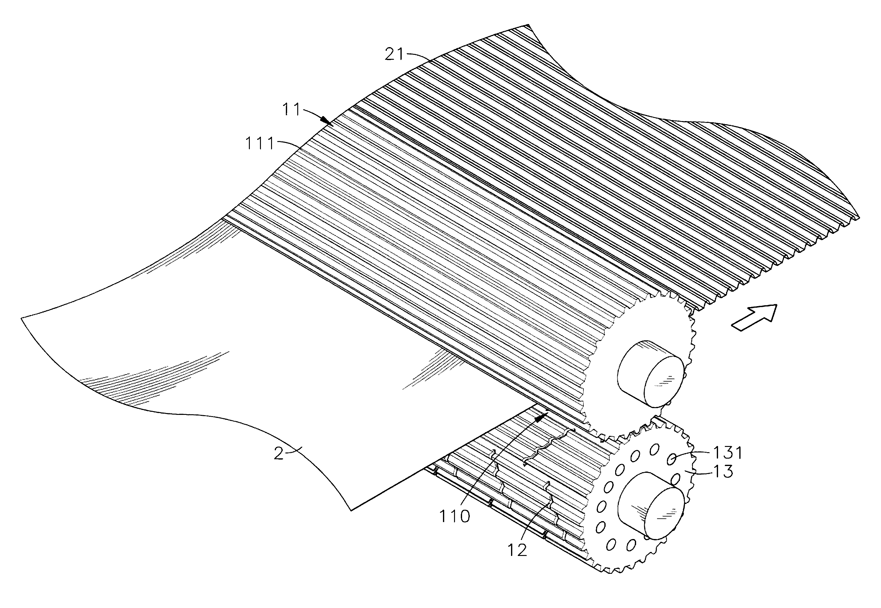
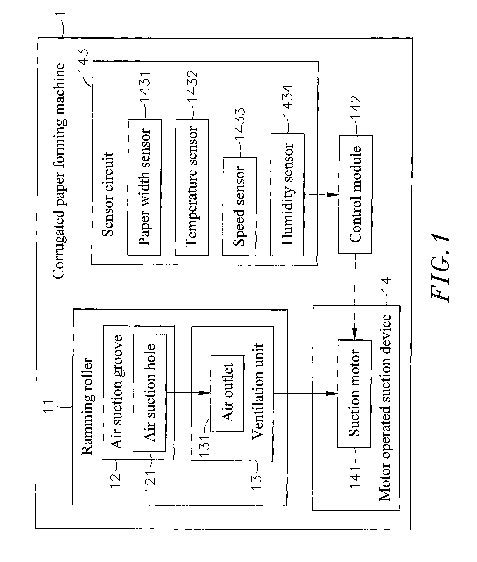
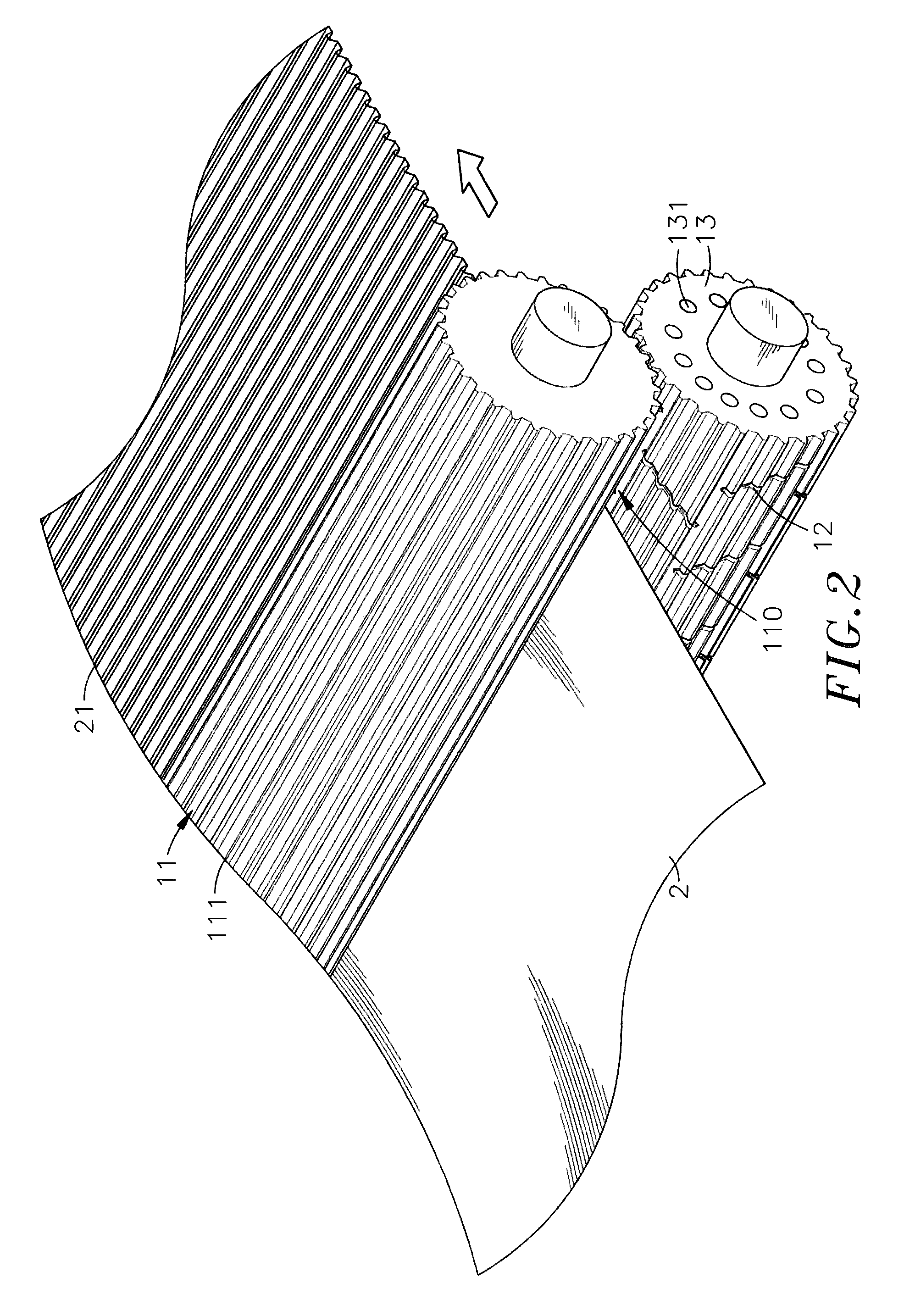
[0015]Referring to FIGS. 1-3, a system block diagram of a corrugated paper forming machine in accordance with a first embodiment of the present invention, a schematic drawing illustrating a paper material delivered through ramming rollers of the corrugated paper forming machine and rammed into shape in accordance with the first embodiment of the present invention and an enlarged view of a part of one ramming roller of the corrugated paper forming machine in accordance with the first embodiment of the present invention are shown. As illustrated, the corrugated paper forming machine 1 comprises at least one, for example, two ramming rollers 11 arranged in a parallel manner in proximity to each other with a gap 110 left therebetween for the passing of a paper material 2, enabling the applied paper material 2 to be rammed by the ramming rollers 11 to provide a flute design 21. The ramming rollers 11 can be fluted rollers, pressure rolls, guide wheels, etc. In this embodiment, the rammin...


PUM


Abstract

A corrugated paper forming machine includes ramming rollers for ramming a paper material into a corrugated paper having flute design, each ramming roller including longitudinal teeth equiangularly spaced around the periphery thereof, a plurality of air suction grooves located in the periphery, a ventilation unit formed of a plurality of air outlets and located in one end thereof and air suction holes located in the air suction grooves in communication with the air outlets, a motor operated suction device for drawing air out of the ramming rollers to cause generation of a suction force in the air suction grooves, a control module, a sensor circuit for sensing operation conditions of the supplied paper material providing detected numerical data to the control module to regulate the speed of the suction motor in changing the level of suction force.

Description

BACKGROUND OF THE INVENTION[0001]1. Field of the Invention[0002]The present invention relates to paper product manufacturing technology and more particularly, to a corrugated paper forming machine with numerical motor speed control, which uses a suction motor of a motor operated suction device to draw air out of the ramming rollers for causing generation of a suction force in air suction grooves of the ramming rollers to suck up the paper material, enables a sensor circuit to detect the operation conditions of the paper material and to provide the detected numerical data to a control module for controlling the speed of the suction motor to regulate the speed of the suction motor in changing the level of suction force.[0003]2. Description of the Related Art[0004]At the present time, the manufacturing industry is facing labor shortages and rising awareness of environmental protection, rising of labor and operating costs and pressure of transition of labor-intensive nature of manufactu...

Claims


Application Information

Patent Timeline
Patent Type & Authority Patents(United States)
IPC IPC(8): D21G9/00D21F7/00
CPCD21F7/00D21F11/12
Inventor LIN, TZU-CHE
Owner LIN TZU CHE
Why Eureka
Try Eureka