Artifical eye structure and toy having same

a technology of artificial eye and toy, applied in the field of artificial eye structures, can solve the problems of easy damage, noise, and affecting the reality of simulated behavior, and achieve the effect of improving the quality of life and enhancing the quality of li

Inactive Publication Date: 2010-11-18
HONG FU JIN PRECISION IND (SHENZHEN) CO LTD +1
View PDF5 Cites 8 Cited by
  • Summary
  • Abstract
  • Description
  • Claims
  • Application Information

AI Technical Summary

Problems solved by technology

The eyelids are generally driven to rotate by an electric motor which is noisy and easily damaged.
Reality of simulated behavior is somehow compromised.

Method used


Image

  • Artifical eye structure and toy having same
  • Artifical eye structure and toy having same
  • Artifical eye structure and toy having same

Examples


Embodiment Construction

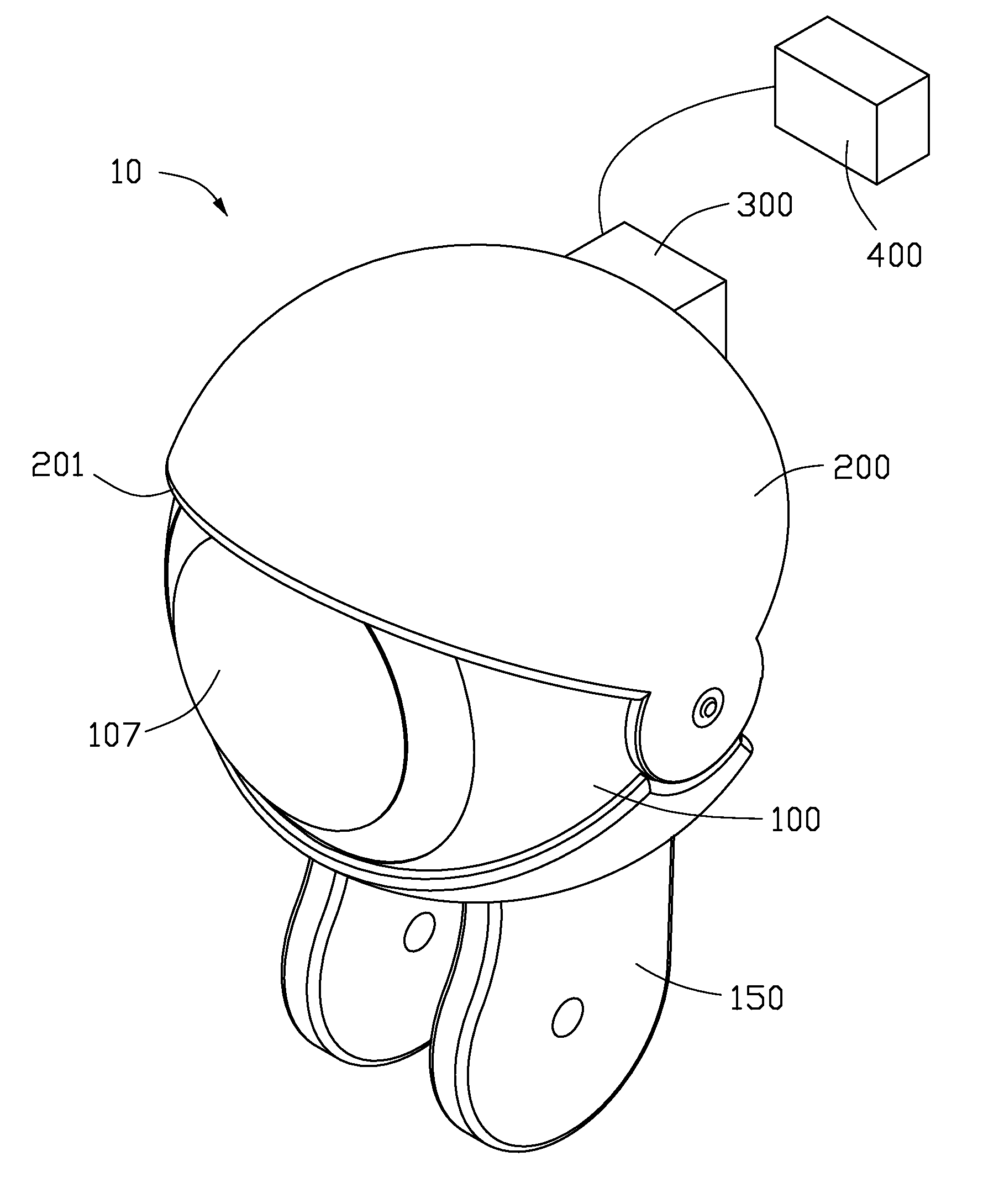
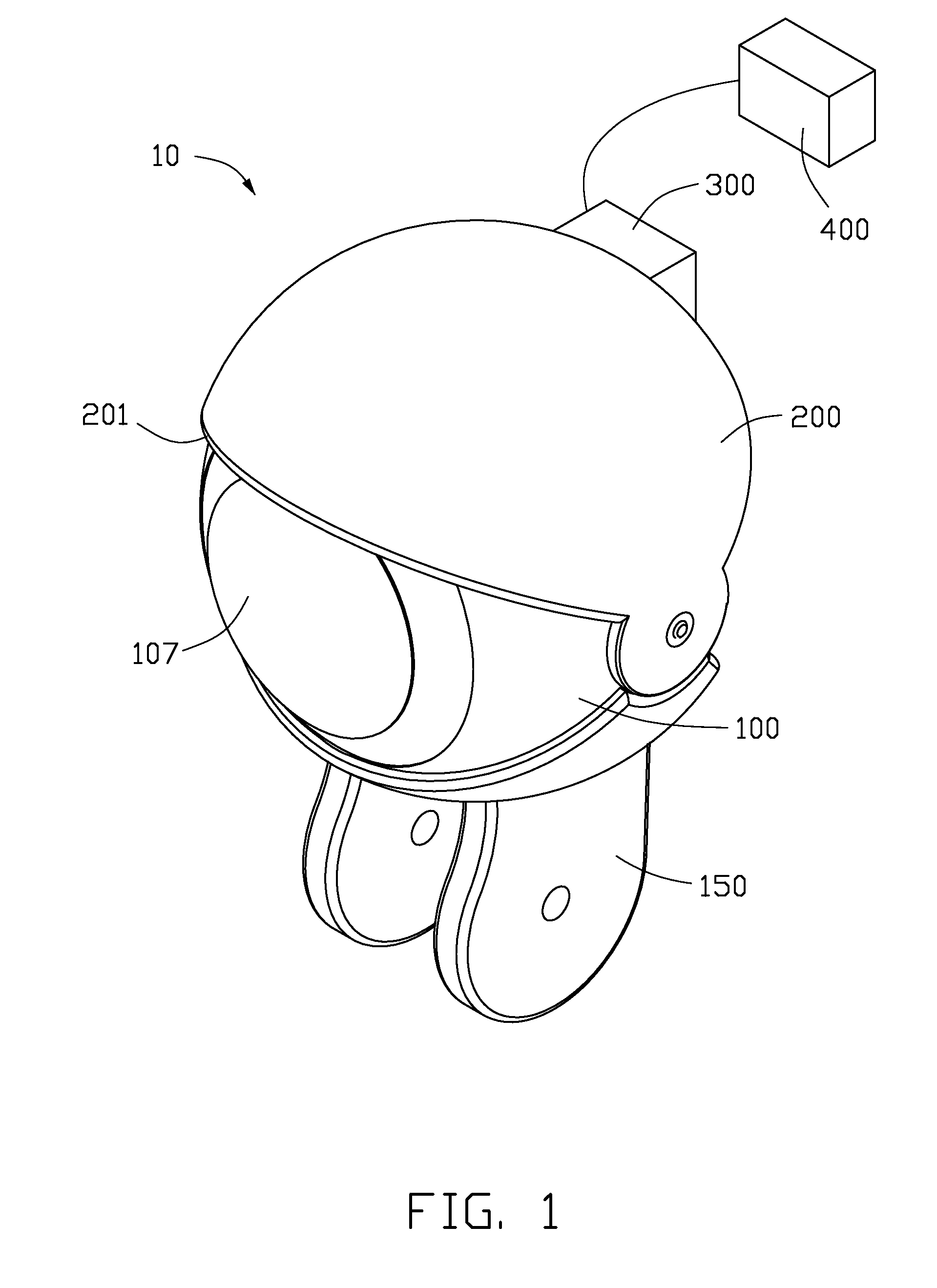
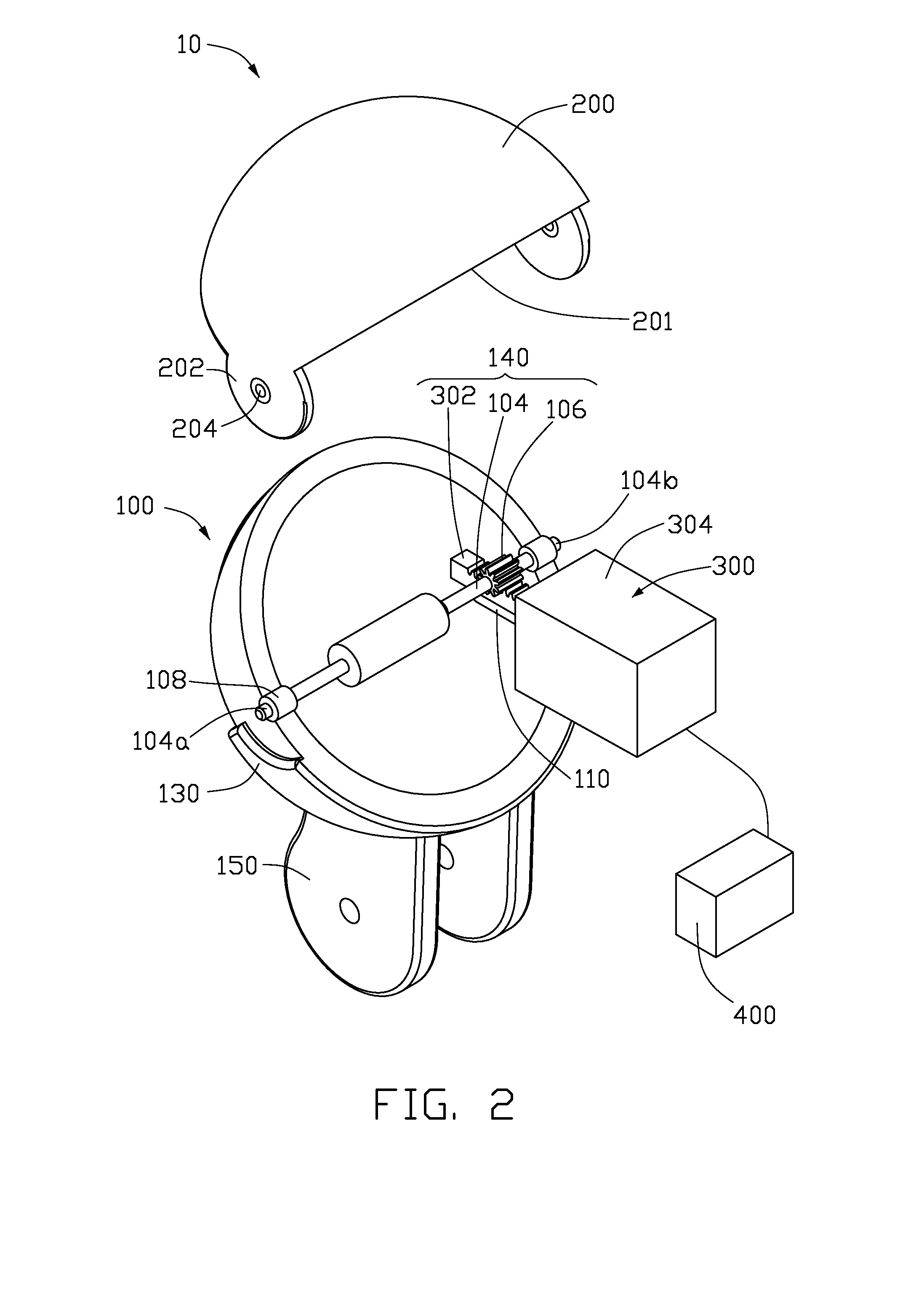
[0012]Referring to FIG. 1 and FIG. 2, an artificial eye structure 10 for use in a toy or robot 500 (see FIG. 5) in accordance with an exemplary embodiment is illustrated. The toy or robot 500 employs a battery 500a (see FIG. 5) for power supply. The artificial eye structure 10 includes an artificial eyeball 100, an artificial upper eyelid 200, an artificial lower eyelid 130, a support portion 150, a transmission device 140, a drive device 300, a spring 306 (see FIG. 4), and a controller 400.

[0013]Also referring to the FIG. 3, the artificial eyeball 100 is substantially a hollow semi-sphere and includes a first inner surface 101, a first outer surface 102, an edge 103, a pair of shaft sleeves 108, and a sliding support 110. The edge 103 is circular. The shaft sleeves 108 are formed at the edge 103. Each of the shaft sleeves 108 is generally a cylinder and defines a pivot hole 108a therethrough. The pivot holes 108a are aligned with each other and define a pivot axis OA substantially ...


PUM


Abstract

An artificial eye structure rotates an artificial upper eyelid via the attraction between a number of electromagnetic elements disposed in a line and a magnet. The rotation angle of the artificial upper eyelid can be controlled by selectively magnetizing the electromagnetic elements.

Description

BACKGROUND[0001]1. Technical Field[0002]The present disclosure relates to artificial eye structures and, particularly, to an artificial eye structure capable of controlling a rotation angle of an artificial upper eyelid thereof.[0003]2. Description of Related Art[0004]Currently, an artificial eye structure for use in a toy / robot typically can rotate eyelids thereof to enhance authenticity of simulated behavior. The eyelids are generally driven to rotate by an electric motor which is noisy and easily damaged. On the other hand, driven by the electric motor, the eyelids are typically kept at either an open state or a close state. Reality of simulated behavior is somehow compromised.[0005]What is needed, therefore, is an artificial eye structure which can overcome the above-mentioned problems.BRIEF DESCRIPTION OF THE DRAWINGS[0006]Many aspects of the present embodiments can be understood with reference to the figures. The components in the figures are not necessarily drawn to scale, th...

Claims


Application Information

Patent Timeline
Patent Type & Authority Applications(United States)
IPC IPC(8): A63H3/40
CPCA63H3/38
Inventor SIP, KIM-YEUNG
Owner HONG FU JIN PRECISION IND (SHENZHEN) CO LTD
Why Eureka
Try Eureka