Electric power distribution methods and apparatus

a technology of electric power distribution and apparatus, applied in the direction of instruments, process and machine control, material dimension control, etc., can solve the problems of commercial power grids refusing to permit large amounts of power, unable or likely to be unable to use commercial power grids as a way to distribute power to other end users, and conspiring to limit or frustrate the use of distributed energy resources

Active Publication Date: 2010-11-18
PARETO ENERGY
View PDF9 Cites 85 Cited by
  • Summary
  • Abstract
  • Description
  • Claims
  • Application Information

AI Technical Summary

Problems solved by technology

There are, however, a number of forces seemingly conspiring to limit or frustrate the use of distributed energy resources.
One problem is that the operators of commercial power grids refuse to permit large amounts of power to be fed into the grid from end-user locations.
This means that if one end-user l

Method used


Image

  • Electric power distribution methods and apparatus
  • Electric power distribution methods and apparatus
  • Electric power distribution methods and apparatus

Examples


Embodiment Construction

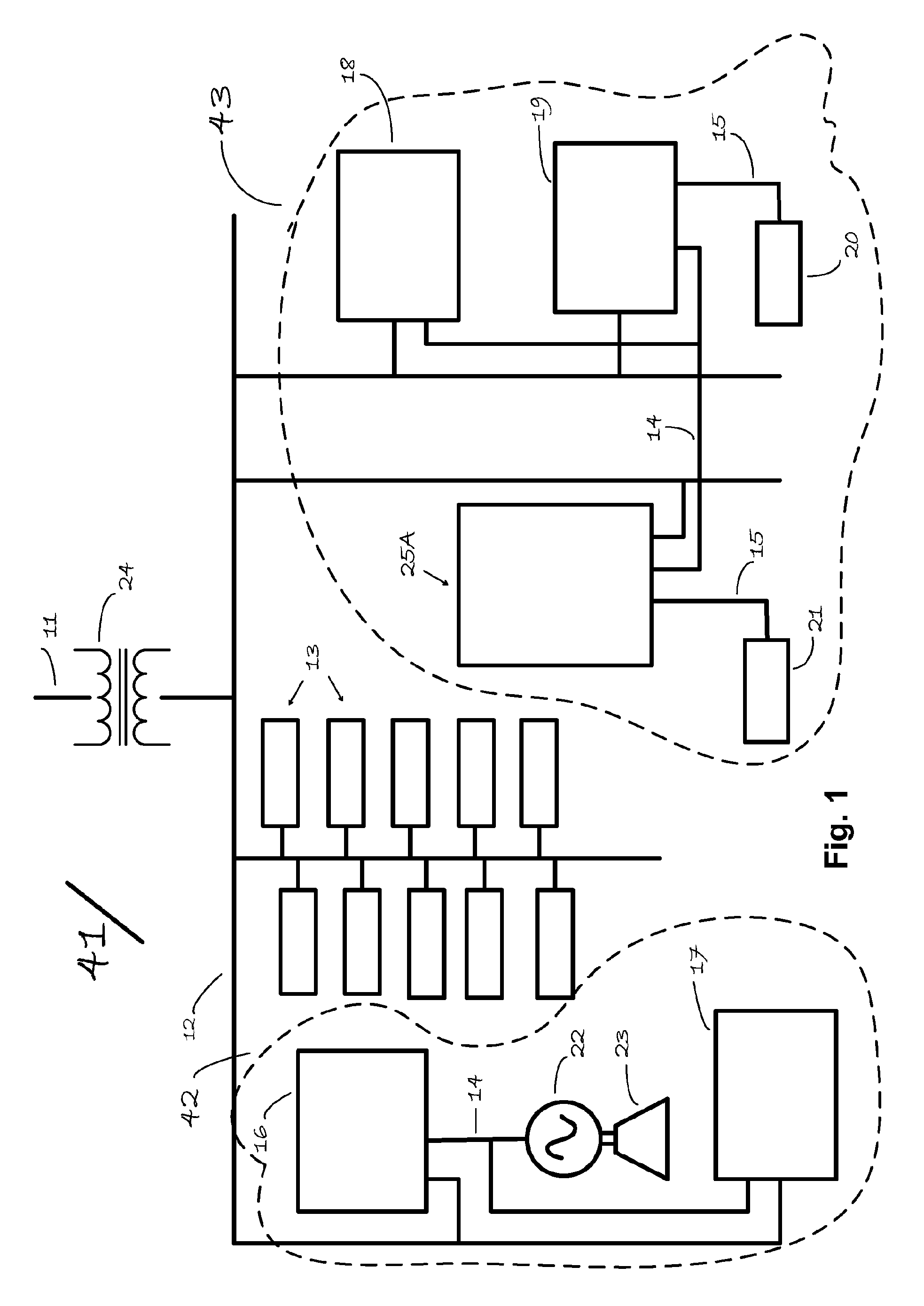
[0019]FIG. 1 shows a small-town distribution system. In an exemplary embodiment, AC power is transmitted to the area by a utility company omitted for clarity in FIG. 1. The power is transmitted to the area by line 11 which may be 115 kilovolts (kV) three-phase AC power. This power is reduced in voltage at a substation 24 operated by the utility company for distribution on a distribution line or grid 12 which may carry 13 kV. This distribution grid is likewise three-phase AC power. Residences 13 are served by the distribution grid 12, as is a medium industrial plant 16, small industries 17, 18, and 19, a shopping mall 25A.

[0020]It may be that the utility company will place a strict limit on the amount of electrical power that any one customer or end user is permitted to generate locally under circumstances that might lead to power being fed back into the utility grid. Such a strict limit may in part be justified by legitimate engineering concerns, and may be in part caused by mindset...


PUM


Abstract

A plurality of end-user locations are served by a commercial utility grid. More than one and less than all of the end-user locations are themselves interconnected by a feeder, the feeder not metallically connected to the utility grid. The end-user locations each have a local AC bus that is not metallically connected to the utility grid or to the feeder, but that is linked by a coupler to both the utility grid and to the feeder. None of the local AC buses or the feeder is required to have the same phase or frequency as the utility grid. Locally generated electric power may be passed by means of the feeder to other end-user locations that are on the feeder. Each local AC bus has two or more inverters powering the bus.

Description

CROSS-REFERENCE TO RELATED APPLICATIONS[0001]This patent application claims priority from U.S. application No. 60 / 996,954 filed Dec. 12, 2007, which application is hereby incorporated herein by reference for all purposes.BACKGROUND[0002]Much attention has been given in recent times to energy policy and energy conservation generally, and to electric power generation and transmission in particular. Traditional models for power generation and distribution may once have been the only workable ways to deliver power to end users. But a variety of factors including political events, rising energy costs, technological progress, and concern for the environment have drawn attention to the need for new paradigms and approaches.[0003]It is apparent that one important goal is to make it possible to draw upon distributed energy resources as a source of electric power for end users. There are, however, a number of forces seemingly conspiring to limit or frustrate the use of distributed energy reso...

Claims


Application Information

Patent Timeline
IPC IPC(8): G06F1/28
CPCH02J3/38H02J3/34H02H7/26
Inventor MCDONNELL, ALAN
Owner PARETO ENERGY
Why Eureka
Try Eureka