Expansion valve with a distributor

Inactive Publication Date: 2010-11-25
DANFOSS AS
View PDF28 Cites 7 Cited by
  • Summary
  • Abstract
  • Description
  • Claims
  • Application Information

AI Technical Summary

Benefits of technology

[0037]The cam shaft may be movable into a position in which at least one of the valve element/valve seat pairs prevents fluid flow to the corresponding flow path. In a preferred embodiment the cam shaft may be moved rotationally in order to simultaneously control flow of fluid medium to each of the parallel outlet openin

Problems solved by technology

This has the disadvantage that it is very difficult to control the flow of refrige

Method used


Image

  • Expansion valve with a distributor
  • Expansion valve with a distributor
  • Expansion valve with a distributor

Examples


first embodiment

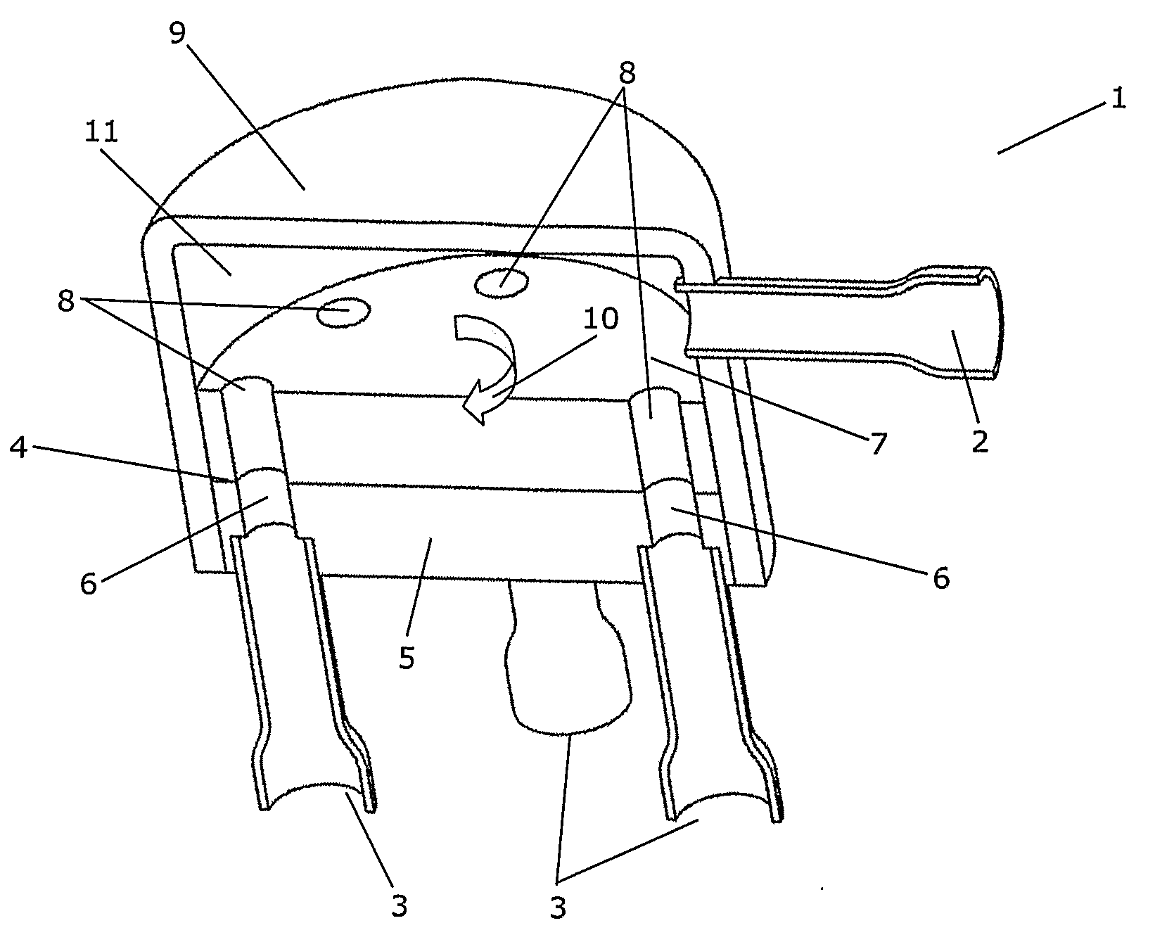
[0069]FIG. 1 is a perspective view of a cut through an expansion valve 1 according to the invention. The expansion valve 1 comprises an inlet opening 2 adapted to receive fluid medium in a liquid state. Thus, the inlet opening 2 is connectable to a source of fluid medium in a liquid state. The expansion valve 1 further comprises four outlet openings 3, three of which are visible, the outlet openings 3 being arranged fluidly in parallel.

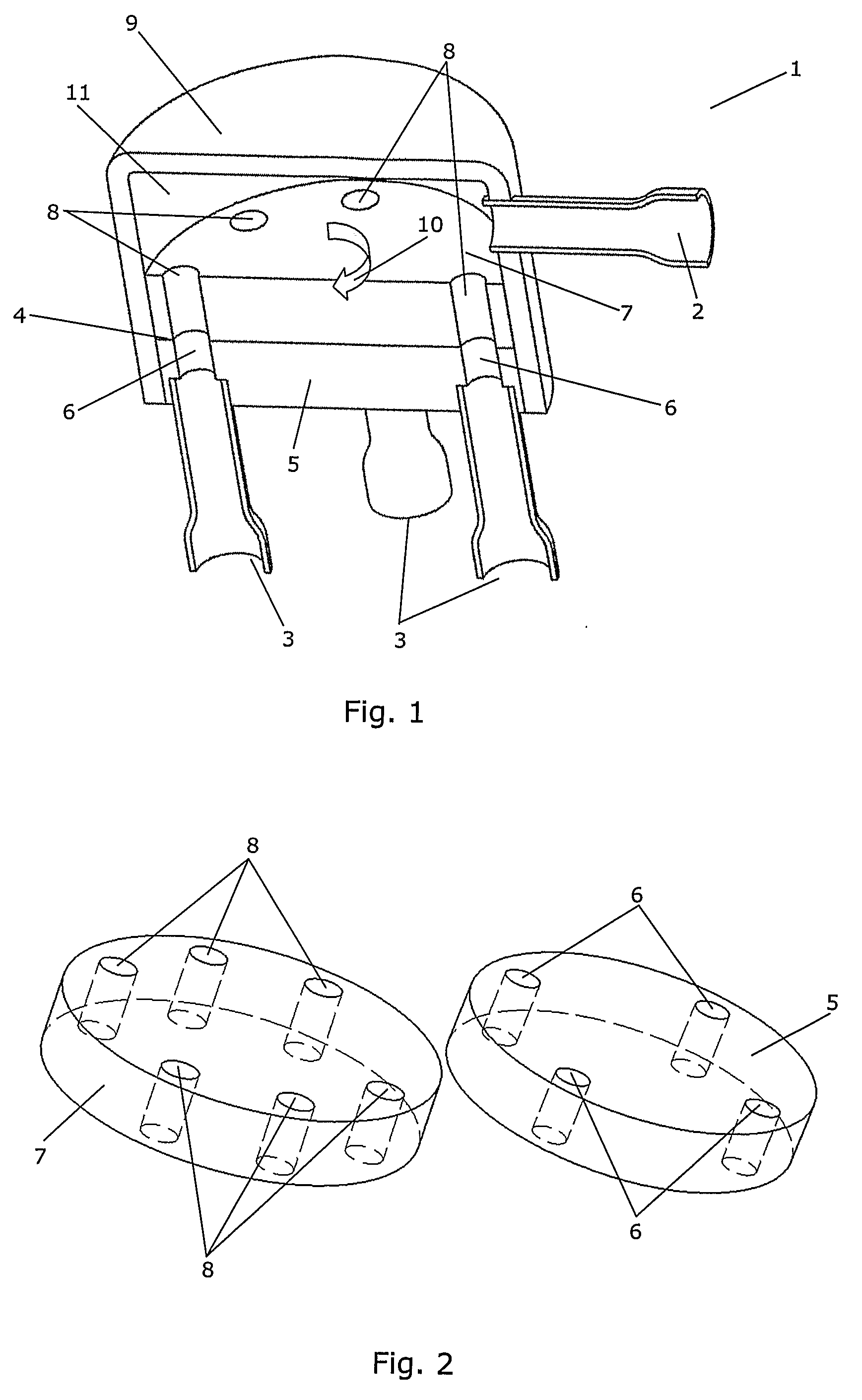
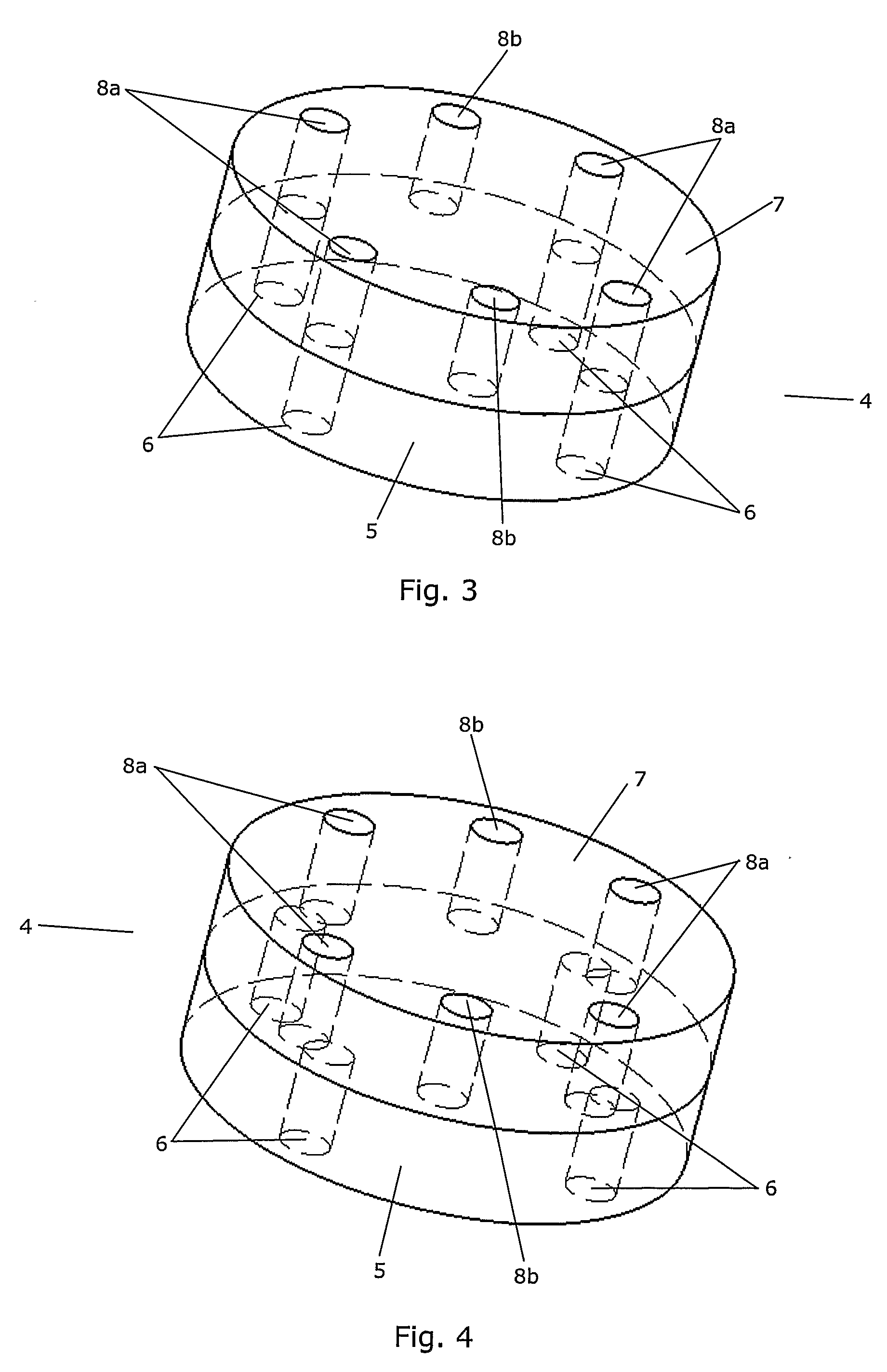
[0070]The expansion valve 1 further comprises a distributor 4 comprising an orifice disk 5 being provided with four openings 6, three of which are visible, and a distributor disk 7 being provided with six openings 8, four of which are visible. The orifice disk 5 is mounted fixedly relative to the outlet openings 3, and each of the openings 6 is arranged at a position corresponding to an outlet opening 3. The distributor disk 7 is arranged rotatably relative to the orifice disk 5 and to a housing 9 of the expansion valve 1, as indicated by arrow 10. Th...

second embodiment

[0080]FIG. 10 is a perspective view of a cut through an expansion valve 1 according to the invention. Similarly to the embodiment shown in FIG. 1, the expansion valve 1 of FIG. 10 comprises an inlet opening 2 and four outlet openings 3, three of which are visible, the outlet openings 3 being arranged fluidly in parallel.

[0081]The expansion valve 1 further comprises a distributor 4 comprising an orifice plate 12 having four valve seats 13 formed therein, three of which are visible. Each of the valve seats 13 is arranged in fluid connection with one of the outlet openings 3.

[0082]The distributor 4 further comprises a movable disk 14 having four valve elements 15 arranged thereon. Two of the valve elements 15 are visible in FIG. 10. Each of the valve elements 15 is arranged at a position corresponding to the position of a valve seat 13. Accordingly, each valve seat 13 / valve element 15 pair forms a valve which is arranged to control fluid flow to an outlet opening 3.

[0083]The movable di...

third embodiment

[0087]FIG. 14 is a perspective view of a cut through an expansion valve 1 according to the invention. The expansion valve 1 of FIG. 14 comprises an inlet opening 2 adapted to receive fluid medium in a liquid state. Thus, the inlet opening 2 is connectable to a source of fluid medium in a liquid state. The expansion valve 1 further comprises six outlet openings 3 being arranged fluidly in parallel.

[0088]The expansion valve 1 further comprises a distributor 4 comprising a cam shaft 18 and six valve seat 13 / valve element 15 pairs, each being fluidly connected to an outlet opening 3. The cam shaft 18 is arranged in abutment with the valve elements 15, and each of the valve elements 15 is biased in a direction towards the cam shaft 18, thereby ensuring tight abutment between the cam shaft 18 and the valve elements 15.

[0089]The cam shaft 18 is arranged rotatably about a centre axis 19. It is shaped in such a manner that the radius of the cross section of the cam shaft 18 varies as a funct...


PUM


Abstract

An expansion valve (1) comprising an inlet opening (2) and a distributor (4) being arranged to distribute fluid medium received from the inlet opening to at least two parallel flow paths (3). At least two outlet openings (3) are adapted to deliver fluid in an at least partially gaseous state, and each outlet opening is fluidly connected to one of the parallel flow paths. A first valve part (7) and a second valve part (5) are arranged movably relative to each other in such a manner that the mutual position of the first valve part and the second valve part determines the opening degree of the expansion valve. Since the distributor (4) forms part of the expansion valve, it distributes the fluid medium to the parallel flow paths prior to or during expansion of the fluid medium, i.e. while the fluid medium is in a substantially liquid state. This makes it easier to control the distribution of fluid medium to the parallel flow paths in a uniform manner.

Description

CROSS REFERENCE TO RELATED APPLICATIONS[0001]This application is entitled to the benefit of and incorporates by reference essential subject matter disclosed in International Patent Application No. PCT / DK2008 / 000219 filed on Jun. 17, 2008 and German Patent Application No. 10 2007 028 563.0 filed Jun. 19, 2007 and Danish Patent Application No. PA 200800425 filed Mar. 19, 2008.FIELD OF THE INVENTION[0002]The present invention relates to an expansion valve, in particular for use in a refrigeration system. More particularly, the present invention relates to an expansion valve having a distributor arranged to distribute fluid medium received from an inlet opening to at least two parallel flow paths.BACKGROUND OF THE INVENTION[0003]In a fluid circuit, such as a refrigerant circuit of a refrigeration system, it is sometimes desirable to split the flow path into two or more parallel flow paths along part of the fluid circuit. This is, e.g., the case in refrigeration systems comprising two or...

Claims


Application Information

Patent Timeline
IPC IPC(8): F25B41/04F25B1/00
CPCF25B39/028F25B2600/2511F25B41/062F16K11/04F16K11/074F16K31/52416F16K11/166F25B41/385F25B41/31F25B41/45F25B41/48
Inventor THYBO, CLAUSBRAM, LEOPAWLIK, JENS
Owner DANFOSS AS
Why Eureka
Try Eureka