Driving support apparatus

Active Publication Date: 2010-11-25
TOYOTA JIDOSHA KK
View PDF8 Cites 86 Cited by
  • Summary
  • Abstract
  • Description
  • Claims
  • Application Information

AI Technical Summary

Benefits of technology

[0008]In view of the above-described situation, the present invention was made. An object of the present invention is to provide a

Problems solved by technology

However, in a case where the lane markings cannot be detected, it may occur that the driving support information cannot be accurately notified.
However, since in the partition line recognition apparatus disclosed in Japanese Patent Application Laid-Open Publication No. 2003-44836, the position of the lane marking on the side, which is not detected, is estimated based on the data of the road width o

Method used


Image

  • Driving support apparatus
  • Driving support apparatus
  • Driving support apparatus

Examples


first embodiment

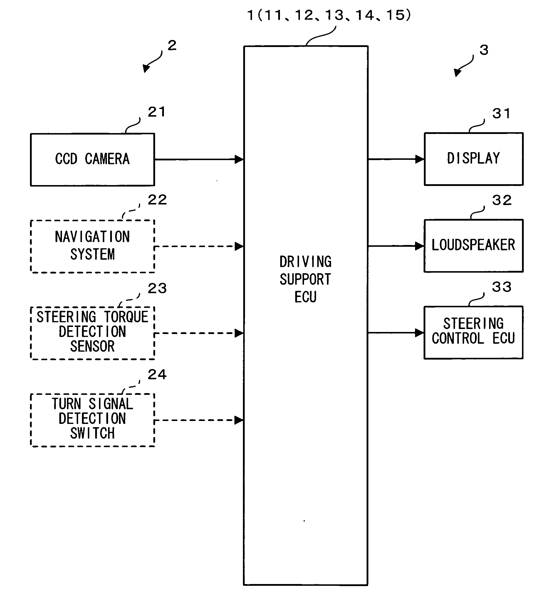
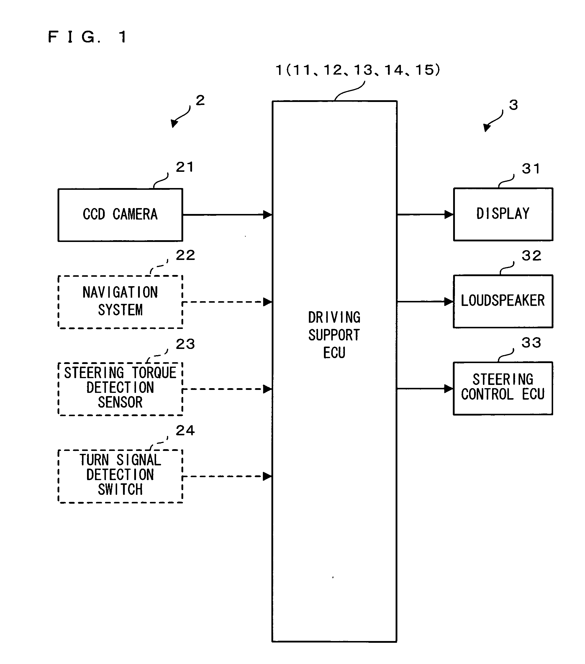
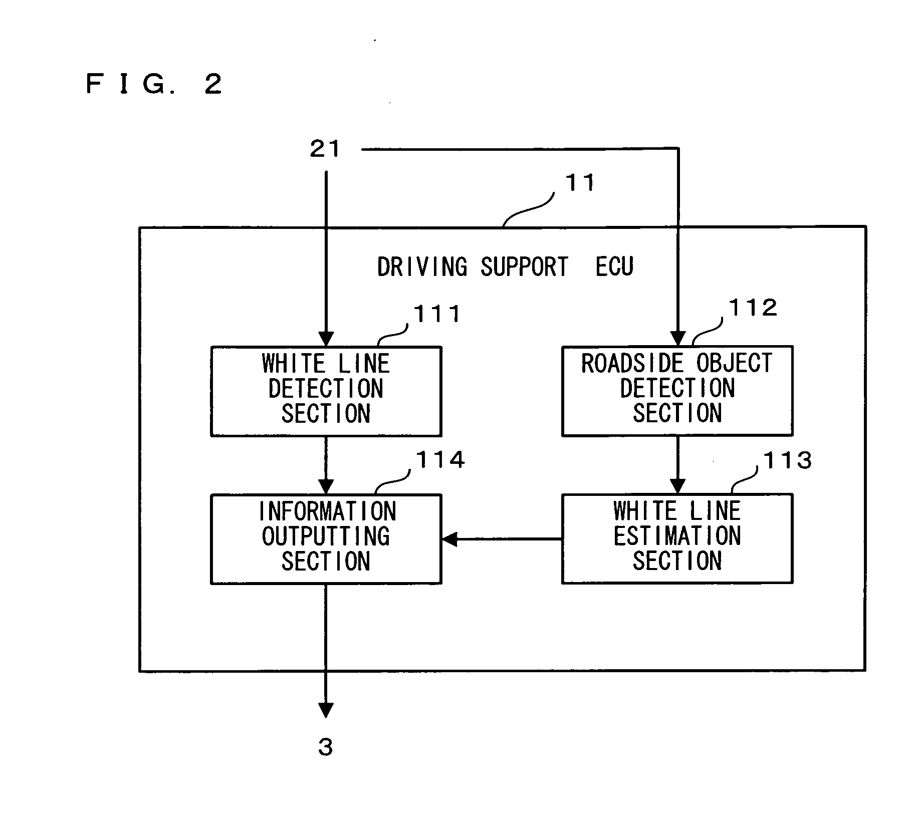
[0113]FIG. 2 is a block diagram illustrating one example of a functional configuration of a driving support ECU 11 according to a first embodiment. As shown in FIG. 2, the driving support ECU 11 comprises as functional parts: a white line detection section 111; a roadside object detection section 112; a white line estimation section 113; and an information outputting section 114.

[0114]The driving support ECU 11 causes a microcomputer provided in an appropriate place of the driving support ECU 11 to execute a control program previously stored in a ROM (Read Only Memory) or the like provided in an appropriate place of the driving support ECU 11, thereby causing the microcomputer to function as the functional parts of the white line detection section 111, the roadside object detection section 112, the white line estimation section 113, the information outputting section 114, and the like. Hereinafter, with reference to FIG. 3, the functional parts of the driving support ECU 11 will be ...

second embodiment

[0131]FIG. 5 is a block diagram illustrating one example of a functional configuration of a driving support ECU 12 according to a second embodiment. As shown in FIG. 5, the driving support ECU 12 comprises as functional parts: a white line detection section 121; a roadside object detection section 122; a distance setting section 123; a virtual lane marking estimation section 124; and an information outputting section 125.

[0132]The driving support ECU 12 causes a microcomputer provided in an appropriate place of the driving support ECU 12 to execute a control program previously stored in a ROM or the like provided in an appropriate place of the driving support ECU 12, thereby causing the microcomputer to function as the functional parts of the white line detection section 121, the roadside object detection section 122, the distance setting section 123, the virtual lane marking estimation section 124, the information outputting section 125, and the like. Hereinafter, with reference to...

third embodiment

[0151]FIG. 8 is a block diagram illustrating one example of a functional configuration of a driving support ECU 13 according to a third embodiment. As shown in FIG. 8, the driving support ECU 13 comprises as functional parts: a white line detection section 131; a lane determination section 132; a center line estimation section 133; and an information outputting section 134.

[0152]The driving support ECU 13 causes a microcomputer provided in an appropriate place of the driving support ECU 13 to execute a control program previously stored in a ROM or the like provided in an appropriate place of the driving support ECU 13, thereby causing the microcomputer to function as the functional parts of the white line detection section 131, the lane determination section 132, the center line estimation section 133, the information outputting section 134, and the like. Hereinafter, with reference to FIG. 9, the functional parts of the driving support ECU 13 will be respectively described.

[0153]FI...


PUM


Abstract

A driving support ECU comprises: a roadside object detection section for detecting, in a case where a lane marking WR on at least one of the right side and left side is detected by a white line detection section and another lane marking WL is not detected, a roadside object GL on the other of the right side and left side; a white line estimation part for estimating a position of a lane marking VL1 on the other of the right side and the left side based on the detected roadside object GL; and an information outputting section for determining a departure from the lane in which the vehicle VC is running, based on the estimated position of the lane marking VL1 on the other of the right side and left side.

Description

BACKGROUND OF THE INVENTION[0001]1. Field of the Invention[0002]The present invention relates to a driving support apparatus which is mounted in, for example, a vehicle and operable to output driving support information to a driver.[0003]2. Description of the Background Art[0004]Conventionally, there has been known a technology in which lane markings (so-called while lines) installed on right and left sides of a lane in which a vehicle is running are detected via a CCD (Charge Coupled Device) camera or the like and based on the detected lane markings, a driver is notified of driving support information in order to prevent a departure from the lane. However, in a case where the lane markings cannot be detected, it may occur that the driving support information cannot be accurately notified. In order to solve this problem, a variety of apparatuses, methods, and the like have been proposed (for example, refer to Japanese Patent Application Laid-Open Publication No. 2003-44836).[0005]A ...

Claims


Application Information

Patent Timeline
IPC IPC(8): B60Q1/00G01C21/36
CPCB62D15/025G06K9/00798B62D15/029G06V20/588
Inventor KATAOKA, HIROAKI
Owner TOYOTA JIDOSHA KK
Why Eureka
Try Eureka