Linkage Mechanism between Trigger Valve and Control Valve in Pneumatic Nail Guns

Inactive Publication Date: 2010-12-02
DE POAN PNEUMATIC
View PDF44 Cites 36 Cited by
  • Summary
  • Abstract
  • Description
  • Claims
  • Application Information

AI Technical Summary

Benefits of technology

[0005]In order to overcome aforementioned disadvantages, an object of the present invention is to provide a linkage mechanism between a trigger valve and a pneumatic nail gun, and more particularly, to provide a linkage mechanism that is configured for positioning a control valve at a predetermined posi

Problems solved by technology

The volume of the pressurized air from main valve is limited, the stability is relative low.
Also, the swinging pole is located bet

Method used


Image

  • Linkage Mechanism between Trigger Valve and Control Valve in Pneumatic Nail Guns
  • Linkage Mechanism between Trigger Valve and Control Valve in Pneumatic Nail Guns
  • Linkage Mechanism between Trigger Valve and Control Valve in Pneumatic Nail Guns

Examples


Example

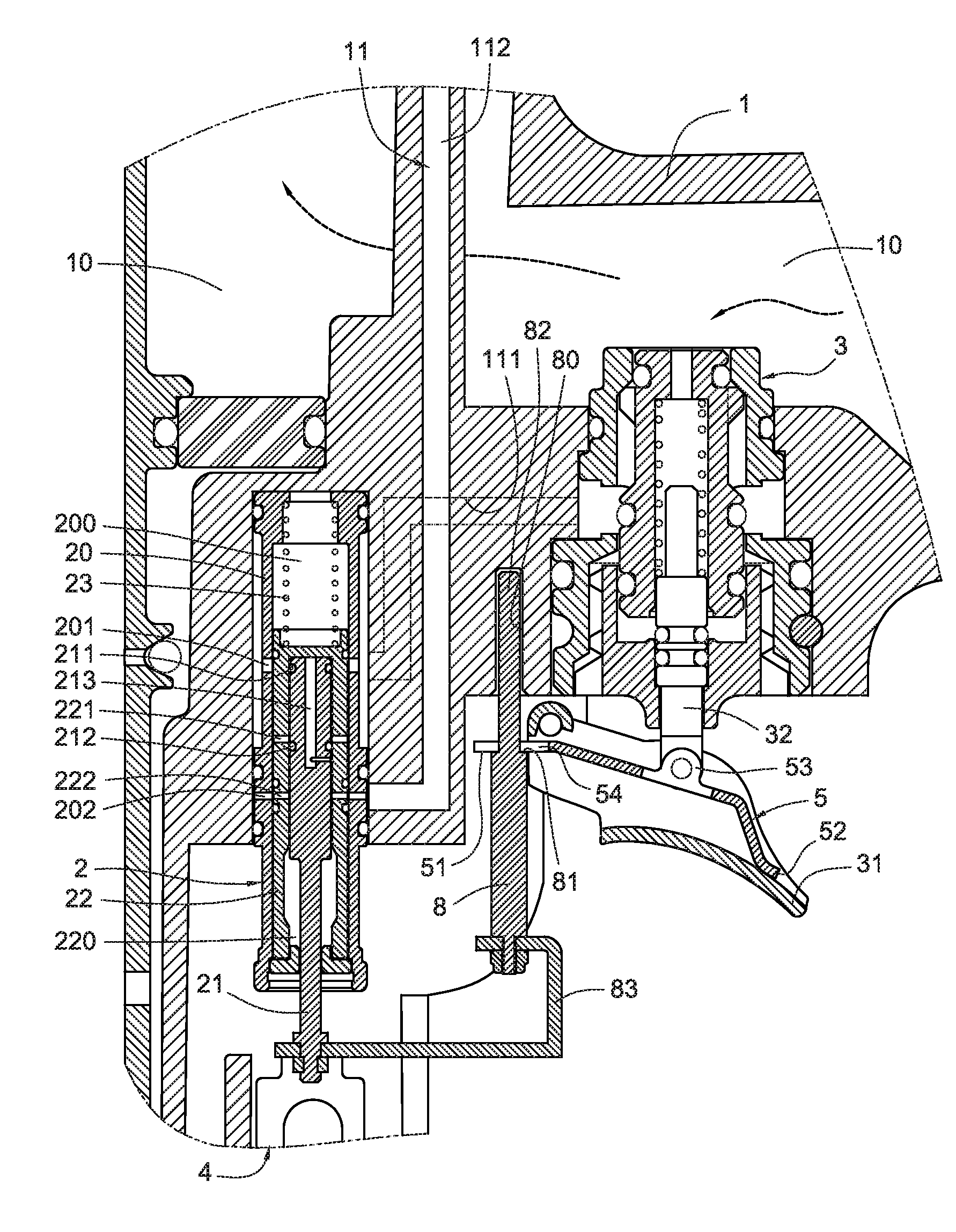
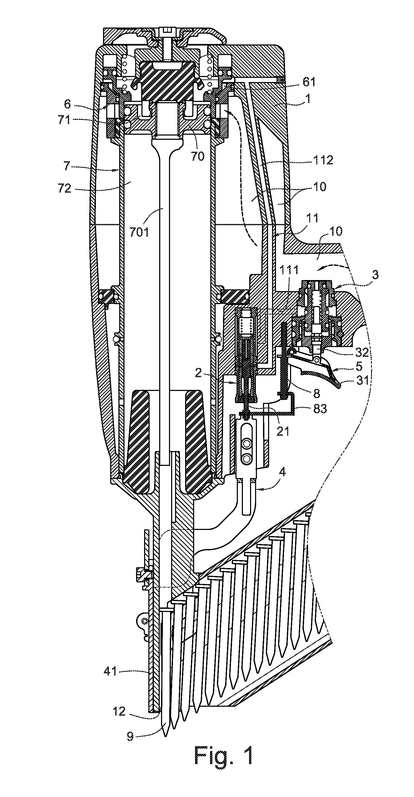
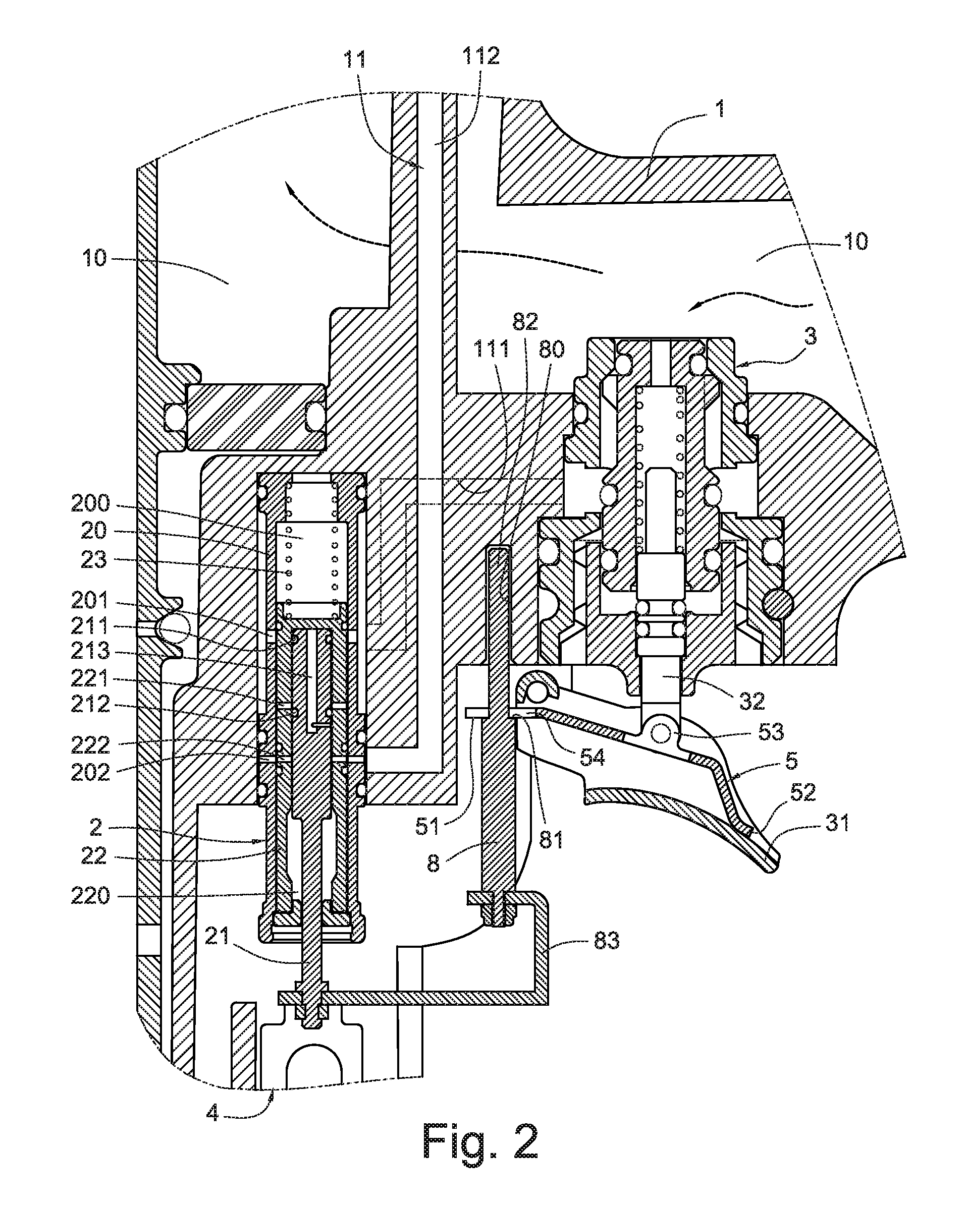
[0043]FIG. 1 illustrates a configuration of a linkage mechanism between a trigger valve and a control valve in a pneumatic nail gun according to the first preferred embodiment of the present invention. Referring to FIG. 2, the pneumatic nail gun includes a main body 1, a control valve 2 and a trigger valve 3 mounted in the main body 1. The control valve 2 includes a valve plug 21. A bottom of the valve plug 21 adjoins a top of a safety rod 4. An outer trigger 31 near to the trigger valve 3 is pivotably mounted at a side thereof. A valve stem 32 of the trigger valve 3 is extended in the outer trigger 31, and an inner trigger 5 is pivotably connected to the bottom end of the valve stem 32 and is disposed in the outer trigger 31. The inner trigger 5 can be swung by pressing the outer trigger 31 (as shown in FIG. 11). A guiding portion 80 is formed at a fixing end near to the outer trigger 31. In the present embodiment, the fixing end is formed on the main body 1, and a top end of a rod...


PUM

PropertyMeasurementUnit
Stabilityaaaaaaaaaa
Durabilityaaaaaaaaaa

Abstract

In a linkage mechanism between a trigger valve and a control valve in a nail gun, the control valve is disposed on a main body of the nail gun. A valve plug of the control valve adjoins to a safety rod of the nail gun. A trigger valve is mounted on the main body and an outer trigger is disposed adjacent to the trigger valve. A valve stem of the trigger valve is extended in the outer trigger. An inner trigger is pivotably connected to a bottom end of the valve stem. An end of a rod member is slidably disposed at a side of the outer trigger and another end of the rod member is connected between the valve plug and the safety rod with an arm. A stopping portion is formed at a middle portion of the rod member. The stopping portion is configured for pressing the outer trigger so as to drive the inner trigger to push the rod member, the arm, the valve plug and the safety rod to move along a nail driving direction of the nail gun. The present linkage mechanism can improve a stability of controlling of nail shooting action and a durability of the nail gun.

Description

BACKGROUND[0001]The present invention relates to control devices for nail hitting of pneumatic nail guns, and particularly to a control device capable of controlling nail hitting action of nail guns according to thickness of workpiece.[0002]Currently, pneumatic nail guns are widely used to join a workpiece (for example, a gasket) onto an object with a nail. The workpiece may include a through hole preformed on it. The users must align a nail with the through hole and then press the nail into the through hole and the object to fix the workpiece. To reduce difficulty of aligning, people developed a nail gun exposing a tip of the nail outside the nail gun.[0003]In addition, different workpieces have different thickness. To provide ability of automatically detecting workpieces that are in predetermined thickness range in pneumatic nail guns, conventionally, the pneumatic nail gun includes a control valve installed in a main passageway. The main passageway usually connects a trigger valv...

Claims


Application Information

Patent Timeline
IPC IPC(8): B25C1/04
CPCB25C1/043B25C1/008
Inventor LIANG, CHIA-SHENGCHEN, YI-HUI
Owner DE POAN PNEUMATIC
Why Eureka
Try Eureka