
Bi-directional overpressure shut-off valve

a technology of bi-directional overpressure and shut-off valve, which is applied in the direction of valve details, valve arrangement, thin material handling, etc., can solve the problem of not having a known valve that implements all of these functions

Active Publication Date: 2010-12-02
HONEYWELL INT INC
View PDF10 Cites 25 Cited by
  • Summary
  • Abstract
  • Description
  • Claims
  • Application Information

AI Technical Summary

Problems solved by technology

Unfortunately, there is no known valve that implements all of these functions.

Method used


Image

  • Bi-directional overpressure shut-off valve
  • Bi-directional overpressure shut-off valve
  • Bi-directional overpressure shut-off valve

Examples


Embodiment Construction

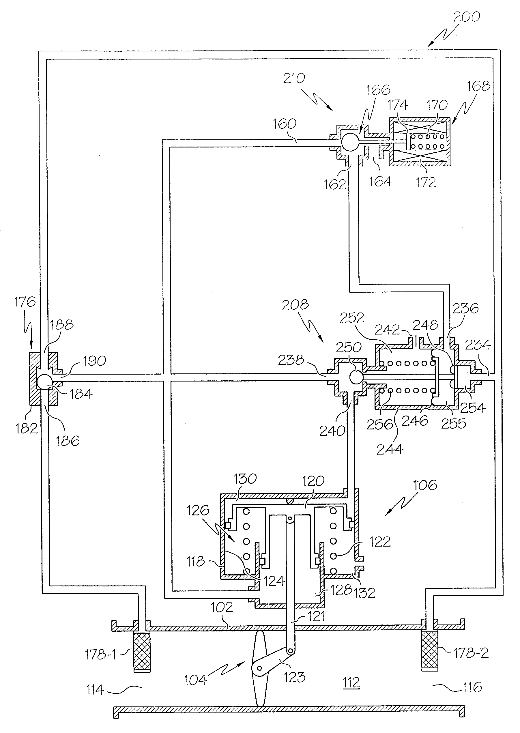
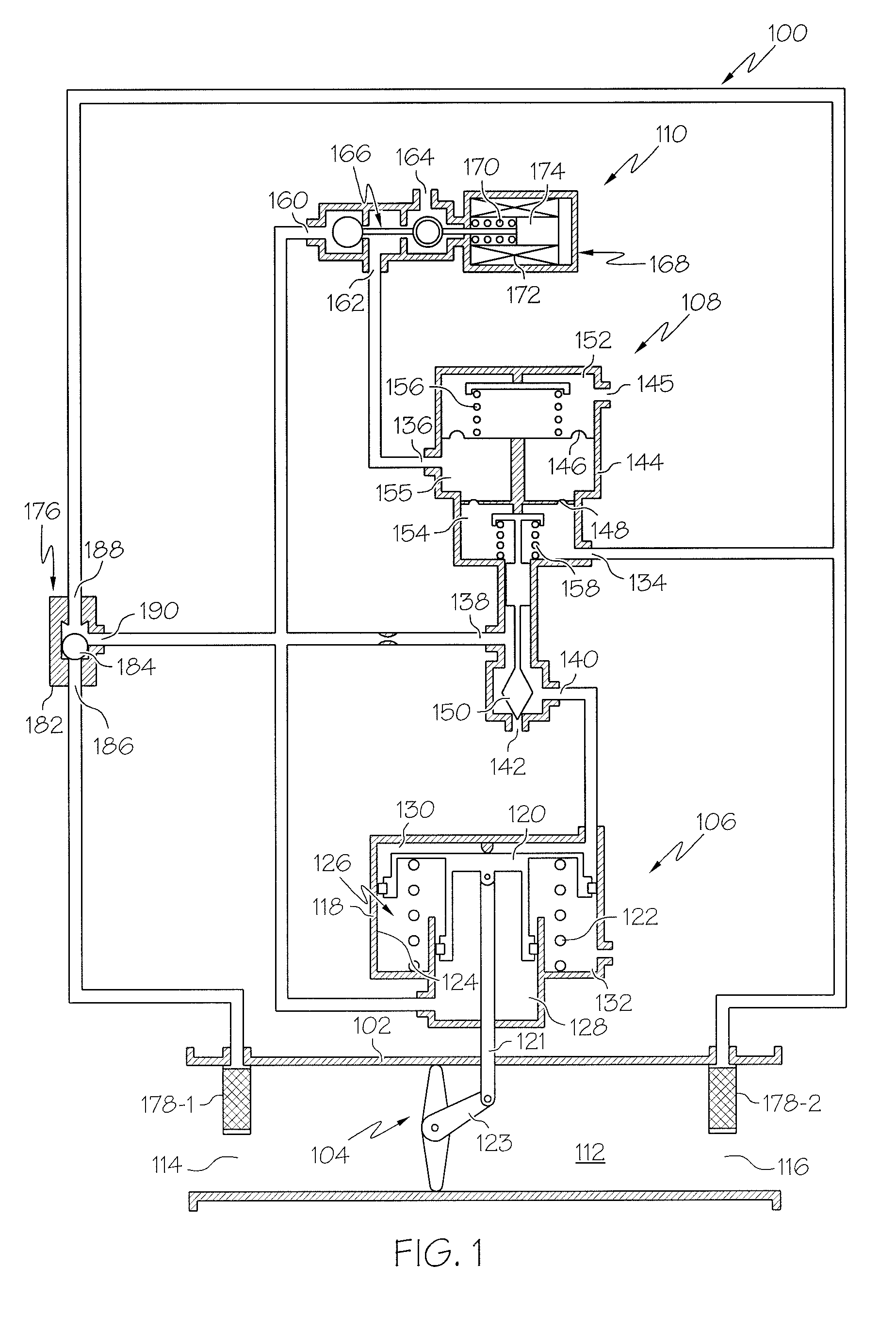
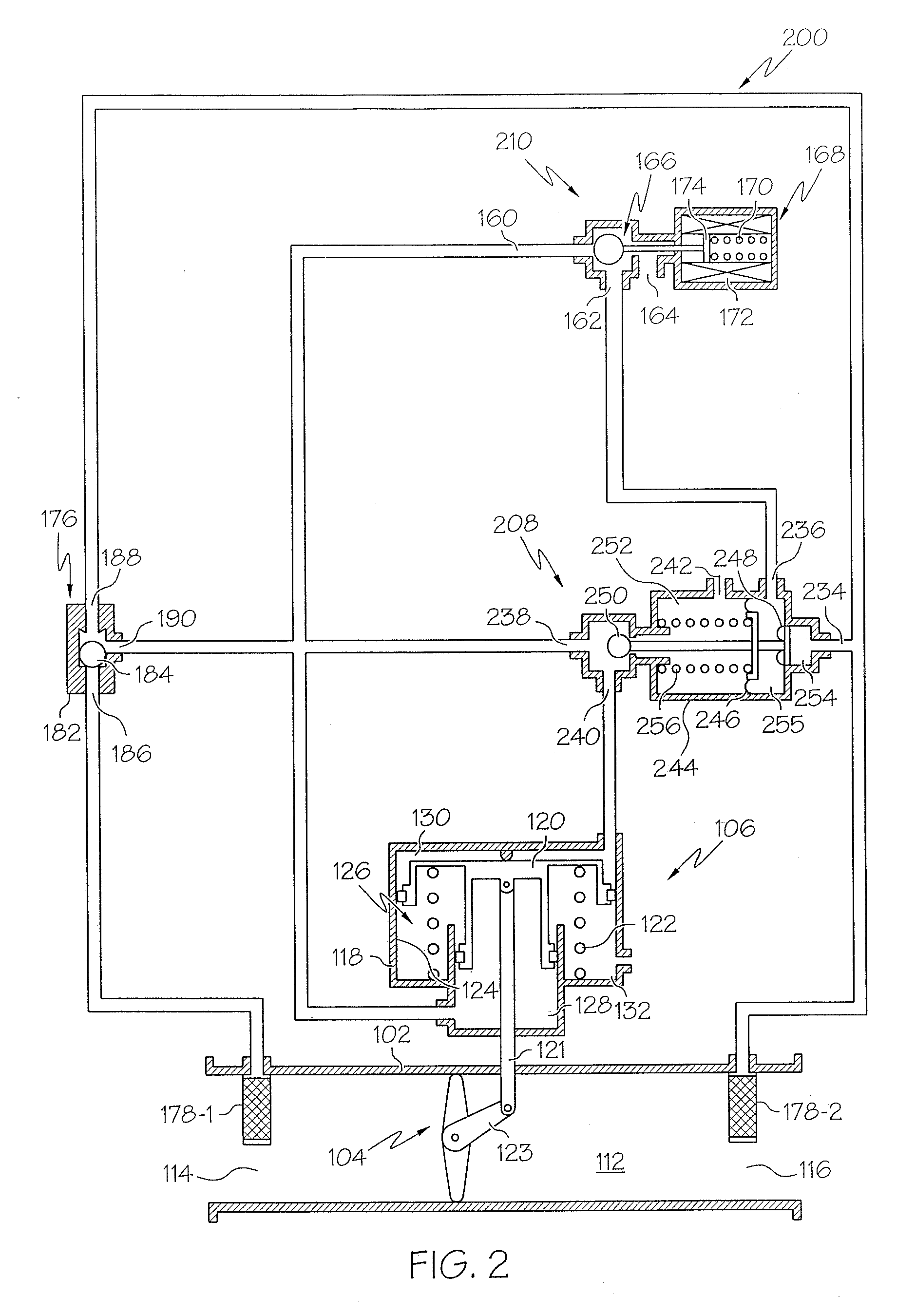
[0011]The following detailed description is merely exemplary in nature and is not intended to limit the invention or the application and uses of the invention. Furthermore, there is no intention to be bound by any theory presented in the preceding background or the following detailed description. In this regard, before proceeding with the detailed description, it should be appreciated that the present invention is not limited to use in conjunction with a specific type of valve. Thus, although the present invention is, for convenience of explanation, depicted and described as being implemented as a fluid-operated butterfly valve, it should be appreciated that it can be implemented as numerous other valve types, and in numerous and varied environments. Moreover, although the preferred operating fluid is air, it should be appreciated that various other gaseous and liquid fluids may also be used.

[0012]Turning now to FIG. 1, a detailed schematic representation of an exemplary embodiment ...


PUM


Abstract

A valve assembly includes a valve body, a valve element, a valve actuator, and a fluid-operated switch. The valve body defines a flow passage. The valve element is disposed at least partially within the flow passage and is moveable between an open position and a closed position. The valve actuator is coupled to the valve element and is responsive to pressurized fluid supplied thereto and vented therefrom to move the valve element between the open position and the closed position, respectively. The fluid-operated switch has a first fluid inlet, a second fluid inlet, a third fluid inlet, an actuator port, and an actuator vent port. The fluid-operated switch is in fluid communication with the valve actuator and is operable to selectively supply pressurized fluid to the actuator via the actuator port, and vent the pressurized fluid from the actuator via the actuator port and the actuator vent port.

Description

TECHNICAL FIELD[0001]The present invention generally relates to fluid-operated valves, and more particularly relates to a fluid-operated valve that includes a back-up shut-off capability to protect downstream components.BACKGROUND[0002]Valves are used in myriad systems and environments, and may be operated in numerous and varied ways. Some valves are manually operated, others are operated via electrical, hydraulic, pneumatic, or various other types of actuators. In one particular implementation, a flow control valve is installed in an aircraft environmental control system. In such an implementation, the flow control valve is operated via a pneumatic actuation device that will open the flow control valve upon receipt of pressurized air upstream of the flow control valve. It may additionally be desirable, in such implementations, that the flow control valve include a shut-off mechanism that prevents downstream flow ducts from reaching or exceeding a particular pressure.[0003]There is ...

Claims


Application Information

Patent Timeline
IPC IPC(8): F16K31/12
CPCF16K31/1245F16K31/423Y10T137/776Y10T137/7761Y10T137/7762
Inventor KRAKE, BRADLEYLAM, CECILIAMATARAZZO, ANTHONYROBERTS, KENNETHBANTA, PAUL
Owner HONEYWELL INT INC
Learn More