Valve actuator apparatus

a valve actuator and actuator technology, applied in the direction of valve details, valve arrangement, spindle sealing, etc., can solve the problems of difficult to determine whether the drift adjustment has been made correctly, damage to the top shaft seal or bearing, and substantial inconvenience, so as to achieve convenient service, simple yet reliable construction, and economic construction

Inactive Publication Date: 2005-02-15
SAFOCO
View PDF30 Cites 56 Cited by
  • Summary
  • Abstract
  • Description
  • Claims
  • Application Information

AI Technical Summary

Benefits of technology

An advantage of the present invention is an economical construction for a valve actuator that is relatively simple yet reliable in construction, and is easy to service.
is an economical construction for a valve actuator that is relatively simple yet reliable in construction, and is easy to service.

Problems solved by technology

However, this is difficult because, among other reasons, such a change also requires changes in up-stop and down-stop adjustments which assure the drift of the gate is positioned correctly in the open and closed position.
If the valve is connected to a christmas tree or is under pressure, it may be difficult to determine whether drift adjustments have been made correctly when replacing the operator since the bore of the valve is not available to receive a drift alignment check tool.
Removal of a valve under pressure in a christmas tree to make drift adjustments may take considerable time and cause substantial inconvenience.
Because the top shaft is often exposed to the atmosphere, it may attract contaminants that cause damage to the top shaft seals or bearings.
As well, torque applied to the top shaft, which may be caused by manual operation, may cause gate, gate seal, or drift misalignment.
Furthermore, changing the top shaft or the top shaft seals has previously required removal of the operator housing.
Another significant problem, especially related to diaphragm-type operators, is leakage of the diaphragms in the region adjacent the top shaft or bonnet stem.
Such leakage may be caused by wear, loss of flexibility, and pinching or wear that occurs should the diaphragm make contact with the diaphragm case.
This leakage may gradually develop, and may slowly reduce the operator power.
In some cases, the positioning of the gate valves in the christmas tree and other types of installations may be restricted because of piping which is supplied to operate an automatic actuator that controls gate movement.
In the past, it has been difficult to use precisely laid piping because the position of the operator fluid port is fixed with respect to the operator housing.
Allowing the operator to rotate with respect to the bonnet could result in leakage or cause misalignment of the up-stop and down-stop drift adjustments of the valve gate.

Method used


Image

  • Valve actuator apparatus
  • Valve actuator apparatus
  • Valve actuator apparatus

Examples


Embodiment Construction

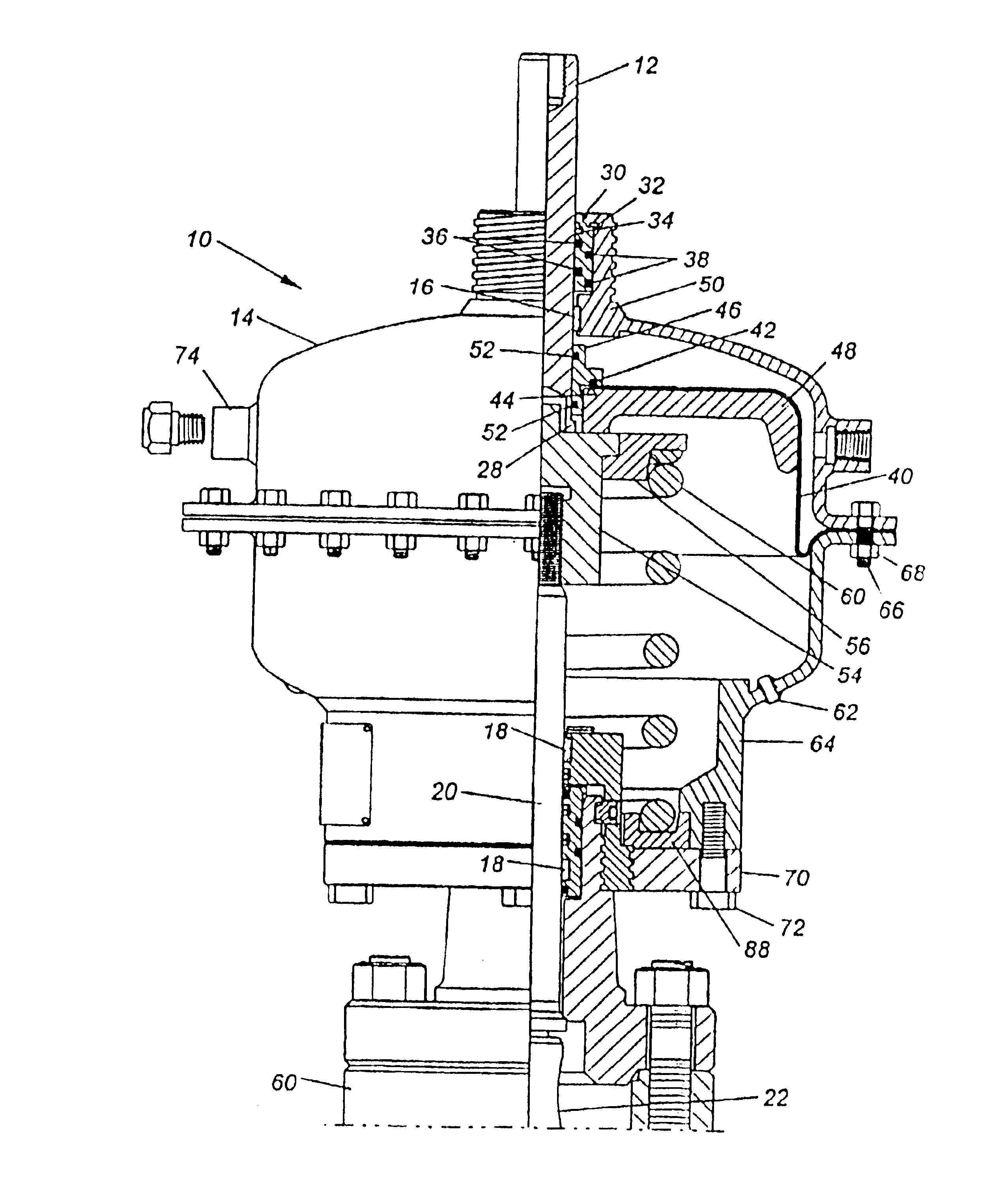
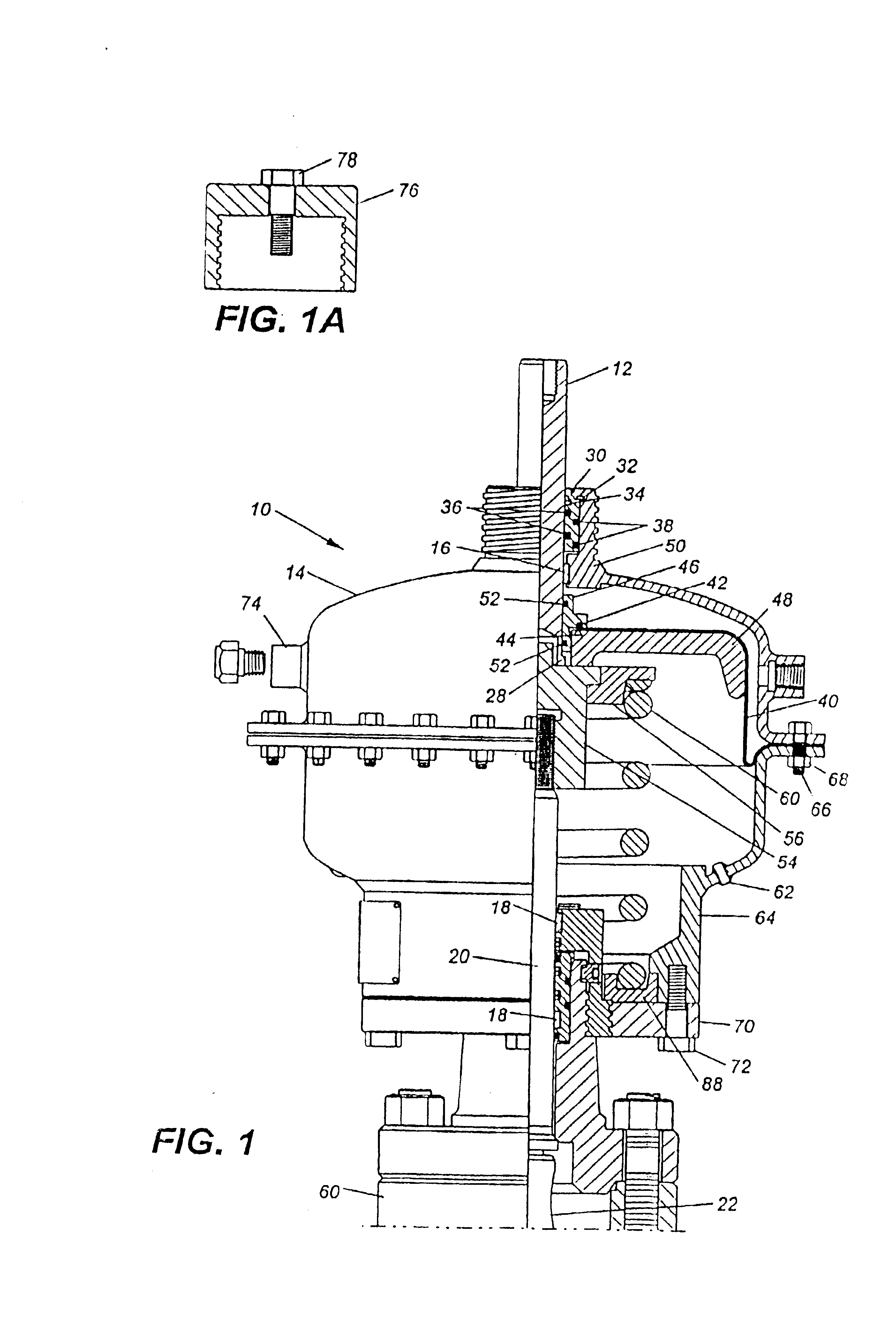
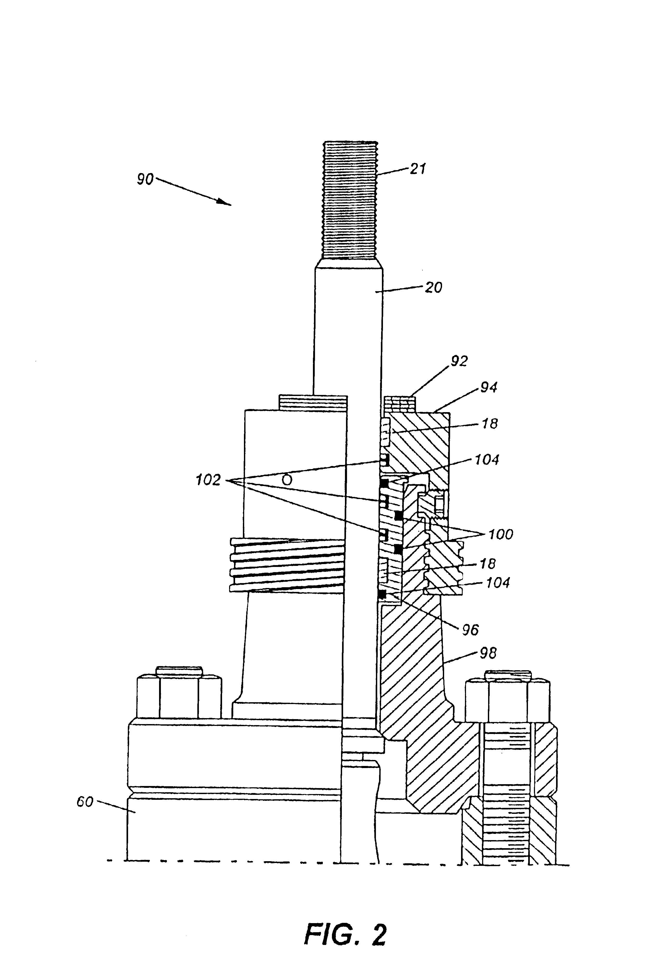
Referring now to the drawings, and more particularly to FIG. 1, a diaphragm-type valve actuator 10 is shown in accord with the present invention. Top shaft 12, which is preferably formed from stainless steel, effectively floats with respect to top diaphragm case 14. As a general matter, all non-stainless metallic components in actuator 10 are preferably coated for protection against environmental conditions. Wear bearing 16, as well as wear bearings 18 (shown in detail in FIG. 2), are preferably non-metallic to eliminate close tolerance problems normally associated with the actuator top shaft and bonnet stem. The wear bearings effectively suspend top shaft 12 and bonnet stem 20 to thereby prevent metallic contact during operation. Thus, the wear bearings are preferably non-metallic and made from relatively hard plastic-like materials, such as Molygard, Nylatron, or Delrin. The wear bearings and other plastic-like components discussed hereinafter may also be made from various plastic...


PUM


Abstract

A valve actuator apparatus and method comprises an operator housing secured to a bonnet assembly. The bonnet assembly is secured to the valve body, and includes a bonnet stem movably within a bonnet housing for moving a gate within the valve body to open and close the valve. A downstop member is fixably secured to the bonnet stem and engages removable stem spacers which are added or removed to obtain a selected bonnet stem drift setting. The operator housing connects to a base ring that surrounds the bonnet housing and rotates to allow positioning of a fluid port in the operator housing. The operator housing may removed and replaced without altering the bonnet stem drift adjustment. A top shaft extends from the operator housing and rotates with respect to the bonnet stem to prevent torque transmission from the top shaft to the bonnet stem. A replaceable sealing cartridge sealingly supports the top shaft for axial movement within the operator housing.

Description

FIELD OF THE INVENTIONThe present invention relates generally to an actuator apparatus and method and, more particularly, to a valve actuator including a bonnet assembly having an improved downstop mechanism that is rotatably free with respect to a floating top shaft and engageable with respect to a replaceable operator without affecting bonnet stem drift adjustment.BACKGROUND OF THE INVENTIONGate valves are generally comprised of a valve body having a central axis aligned with inlet and outlet passages, and a space between the inlet and outlet passages in which a slide, or gate, may be moved perpendicular to the central axis to open and close the valve. In the closed position, the gate surfaces typically seal against sealing rings which surround the fluid passage through the valve body. Gate valves have been used for centuries to control the flow of a great variety of fluids. Often the fluid to be controlled by the gate valve is under pressure. In the petroleum industry, gate valve...

Claims


Application Information

Patent Timeline
Patent Type & Authority Patents(United States)
IPC IPC(8): F16K31/126F16K31/14F16K31/145
CPCF16K31/1262F16K41/04F16K31/145F16K31/1268
Inventor YOUNG, TERRY G.
Owner SAFOCO
Why Eureka
Try Eureka