Zoom optical system

a technology of optical system and zoom lens, applied in the field of zoom optical system, can solve the problems of limiting the miniaturization and reducing the cost of the zoom lens, and achieve the effect of inexpensive construction

Inactive Publication Date: 2007-02-20
FUJI PHOTO OPTICAL CO LTD
View PDF7 Cites 12 Cited by
  • Summary
  • Abstract
  • Description
  • Claims
  • Application Information

AI Technical Summary

Benefits of technology

[0005]The present invention relates to a zoom optical system that is small, that has an inexpensive construction, that assures sufficient movement of the third lens group from the object side for focusing as desired, and that is capable of short-distance photography at the telephoto end.

Problems solved by technology

Japanese Laid-Open Patent Application 2000-131610 operates differently with a zoom lens that includes four lens groups, but the use of the four lens groups limits miniaturization and reduction of the costs of the zoom lens.

Method used


Image

  • Zoom optical system
  • Zoom optical system
  • Zoom optical system

Examples


embodiment 1

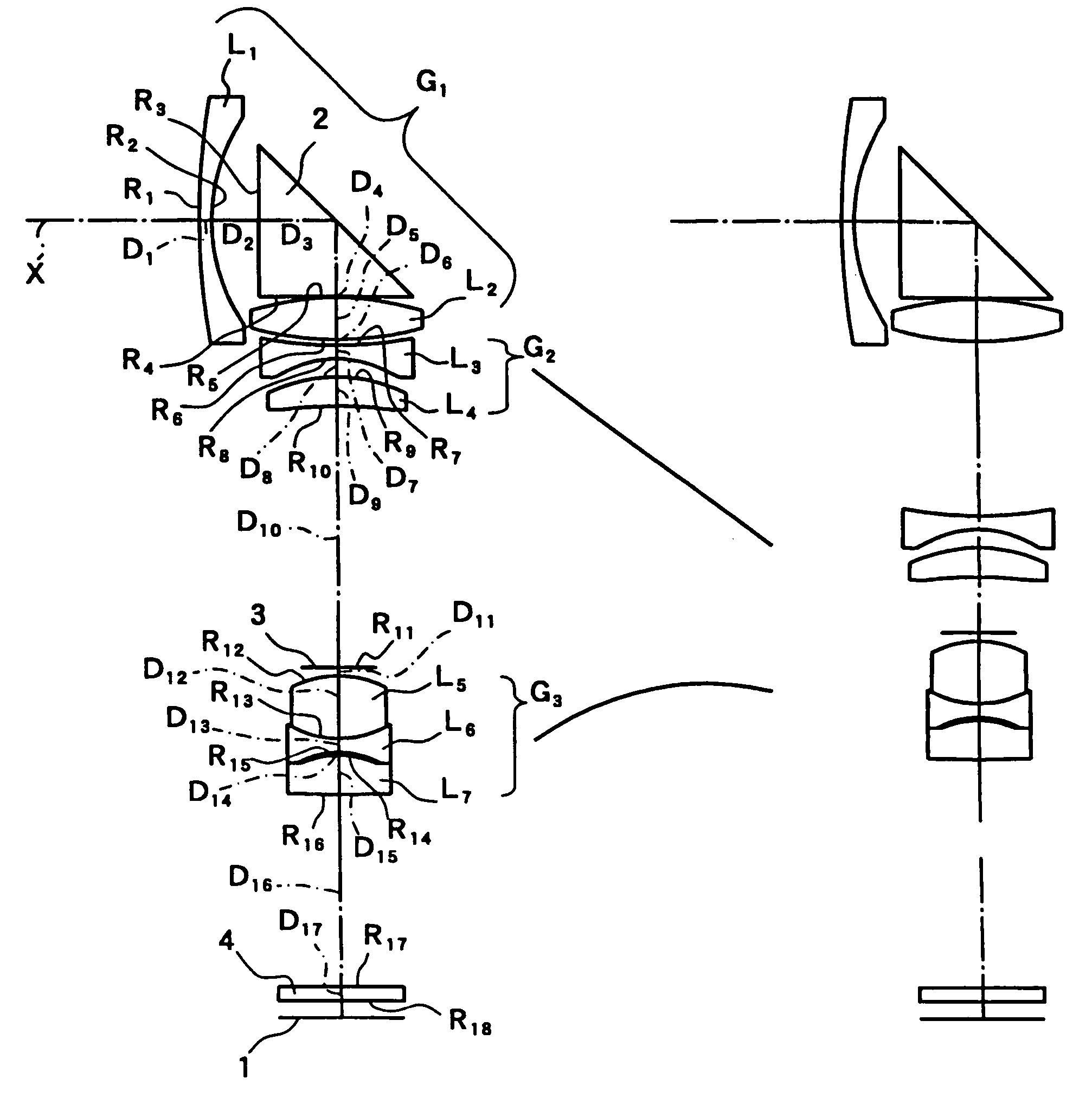
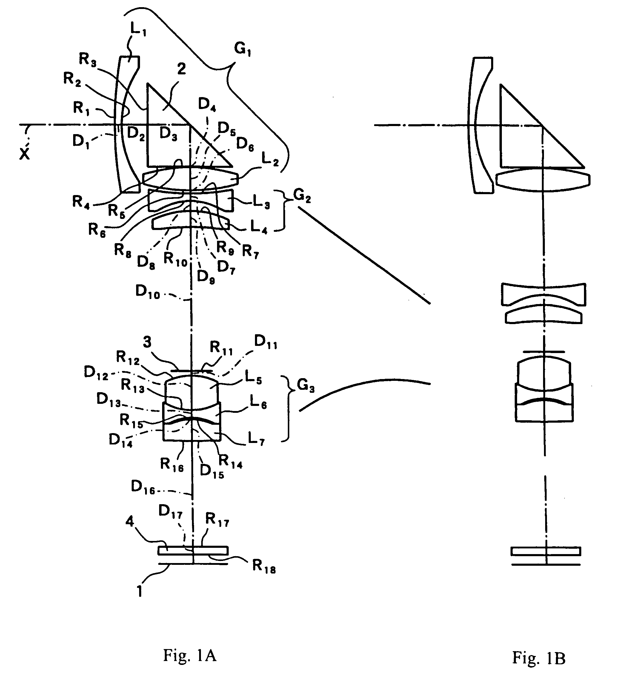
[0034]FIGS. 1A–1B show cross-sectional views of the zoom optical system of Embodiment 1 at the wide-angle end and at the telephoto end, respectively. As shown in FIG. 1A, the zoom optical system of Embodiment 1 includes, arranged in order from the object side, a first lens group G1 having positive refractive power, a second lens group G2 having negative refractive power, and a third lens group G3 having positive refractive power. The straight line adjacent reference symbol G2 and the convex upward line adjacent reference symbol G3 taken together indicate that as the second lens group G2 moves at a constant speed along the optical axis X between the wide-angle end shown in FIG. 1A and the telephoto end shown in FIG. 1B, the third lens group G3 moves at a varying speed along the optical axis X.

[0035]In Embodiment 1, the first lens group G1 includes, arranged in order from the object side, a first lens element L1 having negative refractive power, a meniscus shape, and a convex surface ...

embodiment 2

[0048]FIGS. 3A–3B show cross-sectional views of the zoom optical system of Embodiment 2 at the wide-angle end and at the telephoto end, respectively. Embodiment 2 is similar to Embodiment 1 and therefore only the differences between Embodiment 2 and Embodiment 1 will be explained. Embodiment 2 differs from Embodiment 1 in having a third lens element in the second lens group G2, which becomes the fifth lens element L5 as counted from the object side of the zoom optical system. Embodiment 2 also differs from Embodiment 1 in its lens element configuration by having different radii of curvature of the lens surfaces, different aspheric coefficients of the aspheric lens surfaces, different optical element surface spacings, and some different refractive indexes and Abbe numbers.

[0049]The second lens group G2 includes, arranged in order from the object side, a third lens element L3 having a biconcave shape and a lens component formed of a fourth lens element L4 having a biconcave shape that...


PUM


Abstract

A zoom optical system includes three lens groups, arranged as follows from the object side: a first lens group having positive refractive power, a second lens group having negative refractive power, and a third lens group having positive refractive power. The first lens group includes, arranged as follows along the optical axis, a lens element having negative refractive power, a prism for bending the optical axis, and a lens element having positive refractive power. The second and third lens groups are movable along the optical axis for zooming with only the third lens group reversing its direction of movement along the optical axis during zooming from the wide-angle end to the telephoto end. The third lens group includes a stop, a cemented lens component, and at least one aspheric surface that may be made of plastic. The first lens group also includes at least one aspheric surface.

Description

FIELD OF THE INVENTION[0001]The present invention relates to a zoom optical system used in an image pickup device such as a portable telephone, a portable computer, or a similar device.BACKGROUND OF THE INVENTION[0002]Recently, in devices such as portable telephones and portable computers, picture image information is incorporated in an image pickup device. In an image recording or photographic optical system used in such an image pickup device, it is necessary to make the optical system light-weight and compact in order to obtain the desired portability. When the optical axis of an objective lens extends in the thickness direction of an image pickup device, a technique for reducing the thickness of the casing of the device has been developed that uses a prism to bend the optical axis of the optical system.[0003]On the other hand, additional functionality is also desirable in image recording and photographic optical systems used in such image pickup devices, and image recording and ...

Claims


Application Information

Patent Timeline
Patent Type & Authority Patents(United States)
IPC IPC(8): G02B15/14
CPCG02B15/173G02B15/143105
Inventor ORI, TETSUYA
Owner FUJI PHOTO OPTICAL CO LTD
Why Eureka
Try Eureka