
Propelling transmission control apparatus for a working vehicle having a hydrostatic stepless transmission

Active Publication Date: 2005-02-01
KUBOTA LTD
View PDF16 Cites 13 Cited by
  • Summary
  • Abstract
  • Description
  • Claims
  • Application Information

AI Technical Summary

Benefits of technology

The present invention has been made having regard to the state of the art noted above, and its object is to provide a propelling transmission control apparatus having a relatively inexpensive construction free from any complicated electric systems with sensors for automatically responding to variations in engine load.
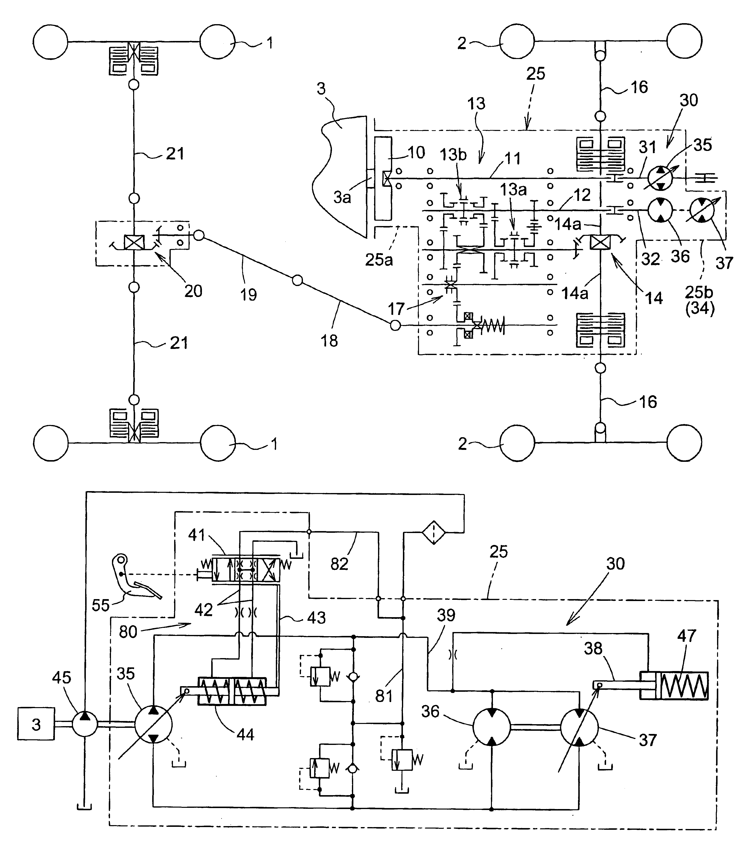
With this construction, the heavier the propelling load becomes, the higher hydraulic pressure in the pressure oil supply line is applied to the main and auxiliary hydraulic motors. Therefore, the swash plate angle of the auxiliary hydraulic motor becomes large by action of the control piston operated by the hydraulic pressure, thereby increasing the volume of the auxiliary hydraulic motor. Thus, the total volume of the main and auxiliary motors is increased while the rotating speed of the common output shaft is reduced. That is, speed is automatically reduced with an increase in the propelling load to increase output torque.
Conversely, the lighter the propelling load becomes, the lower hydraulic pressure in the pressure oil supply line is applied to both the hydraulic motors. Thus, the total volume of the main and auxiliary motors is reduced while the rotating speed of the common output shaft is increased. That is, speed is automatically increased with a decrease in the propelling load.
Hence, it is possible to automatically effect transmission control in response to variations in the load with the relatively inexpensive construction employing only the hydraulic system and not any electric system, which enables the operator to effect a light and smooth driving control.
According to another preferred embodiment of the invention, the hydraulic servomechanism has, applied thereto as a system pressure therefor, a charge pressure for a change speed hydraulic circuit having the main hydraulic pump and the main and auxiliary hydraulic motors. With this construction, a charge oil line for receiving pressure oil from a charge pump is connected to an oil line of the hydraulic servomechanism, thereby to realize a simple servomechanism operable under low pressure.
According to a further preferred embodiment of the present invention, the control device is operatively connected to a speed adjusting device for an engine, the speed adjusting device being operable to a high speed rotation in response to a shifting operation of the control device to high speed drive, and to a low speed rotation in response to a shifting operation of the control device to low speed drive. With this construction, the rotating speed of the engine is reduced in response to the speed change control device operated to low speed drive while being automatically increased in response to the control device operated to high speed drive. Thus, the speed change control device is operated to high speed drive when a load is applied thereby to increase the rotating speed of the hydraulic pump to raise pressure in the hydraulic circuit. As a result, an automatic speed reduction is effected utilizing the auxiliary hydraulic motor to increase output torque. Thus, a change speed operation may be carried out with an excellent accelerating efficiency sensitively responding to the operation of the change speed control device and to quickly increase output torque when a heavy load is applied thereby to enhance driving efficiency.

Problems solved by technology

Therefore, the swash plate angle of the auxiliary hydraulic motor becomes large by action of the control piston operated by the hydraulic pressure, thereby increasing the volume of the auxiliary hydraulic motor.

Method used


Image

  • Propelling transmission control apparatus for a working vehicle having a hydrostatic stepless transmission
  • Propelling transmission control apparatus for a working vehicle having a hydrostatic stepless transmission
  • Propelling transmission control apparatus for a working vehicle having a hydrostatic stepless transmission

Examples


Embodiment Construction

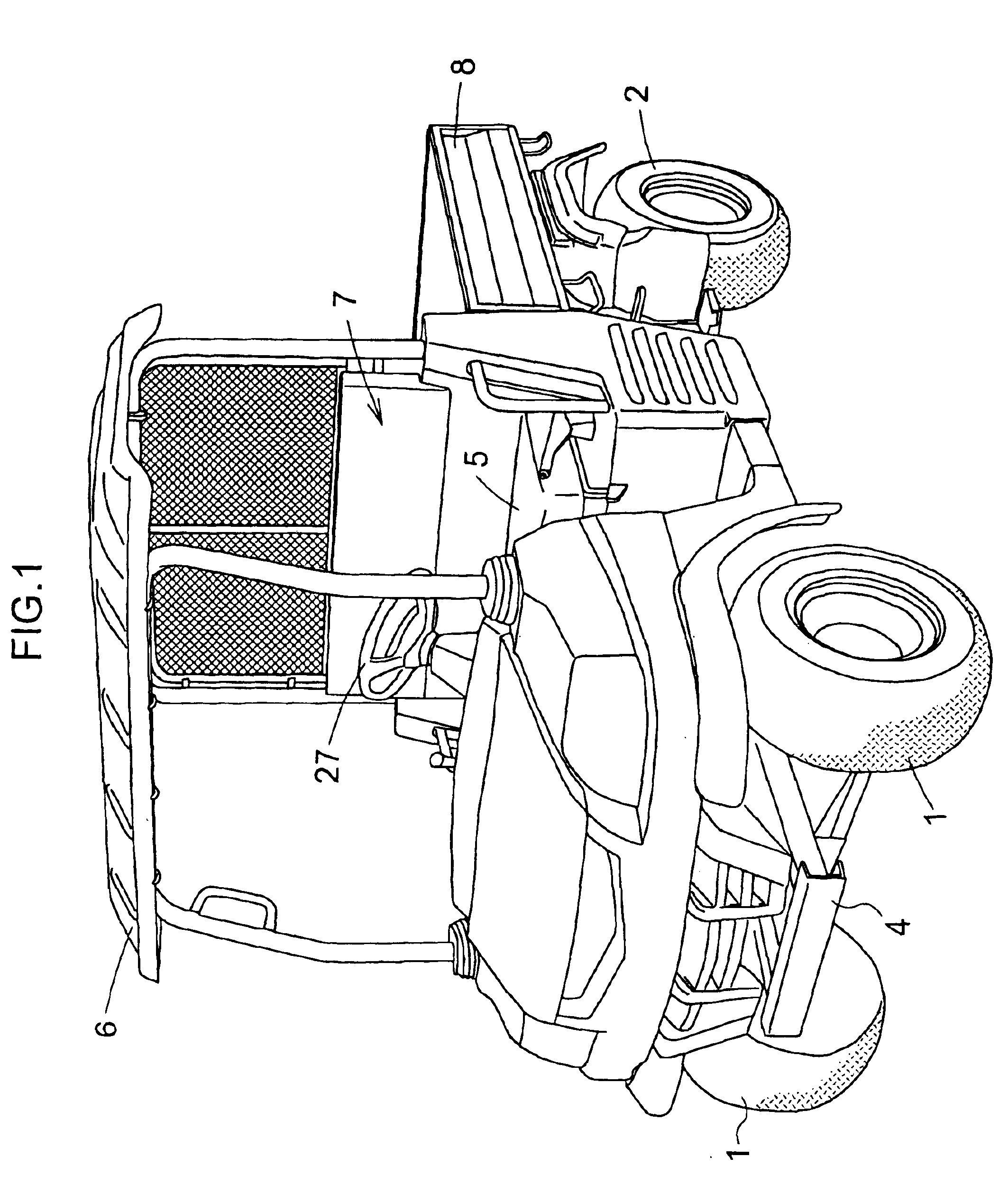
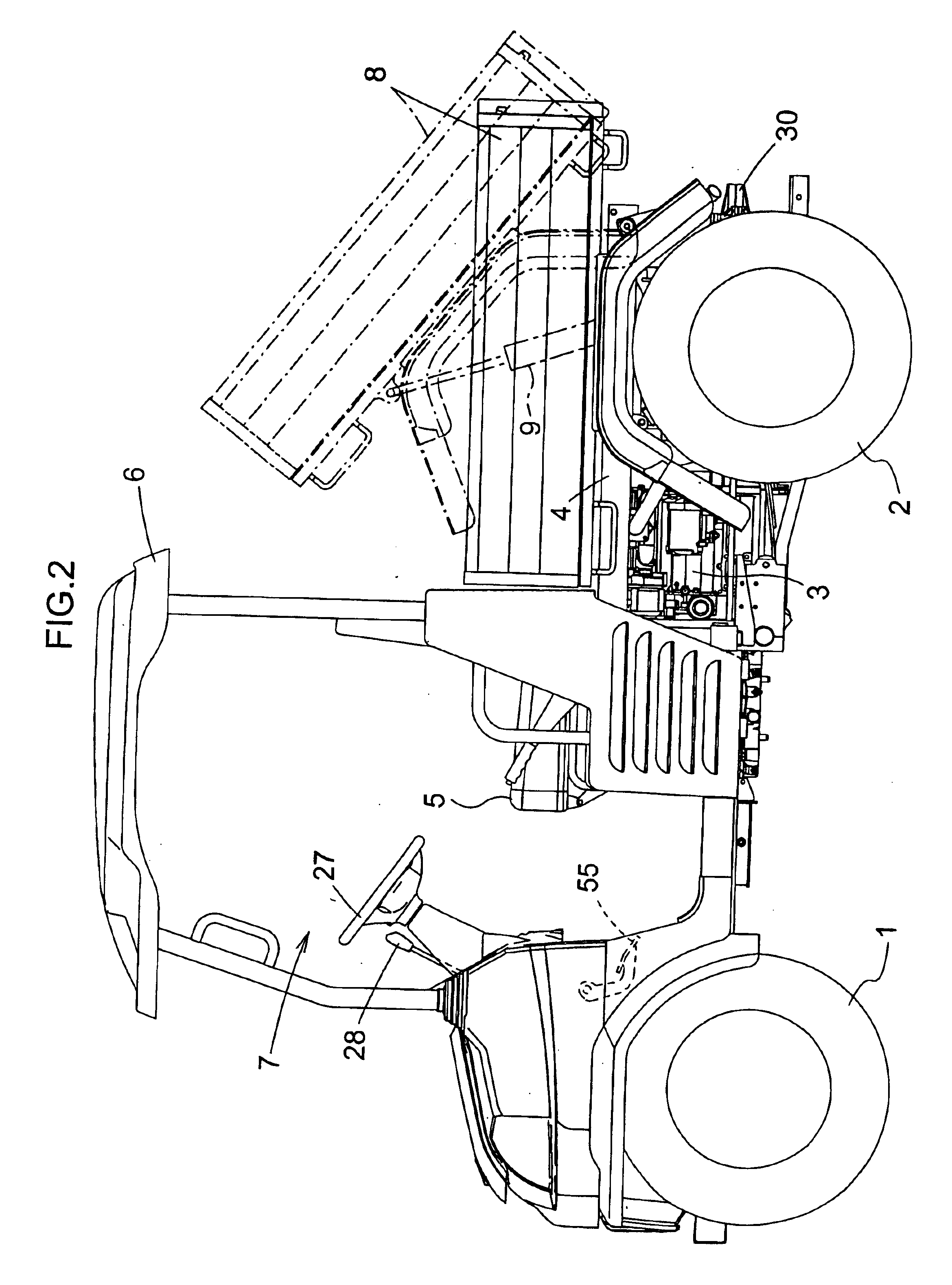
As shown in FIGS. 1 through 3, a working vehicle is supported above the ground by a right and left pair of dirigible front tire wheels 1 and a right and left pair of rear tire wheels 2. The vehicle includes a body frame 4 and an engine 3 mounted on the frame between the front and rear wheels. The working vehicle further includes a driver's section 7 mounted at a front portion of the frame 4 and having a driver's seat 5 and a sunshade 6, and a deck 8 mounted at a rear portion of the frame 4 to be vertically pivotable about a transverse axis disposed at the rear of the deck by a dump cylinder 9.

Output from the engine 3 is transmitted to the front and rear wheels 1 and 2 through a propelling transmission device as shown in FIGS. 4 and 5. More particularly, the output is transmitted from an output shaft 3a with a flywheel 10 mounted rearwardly of the engine 3 to an input shaft 31 of a hydrostatic stepless transmission 30 through a rotary shaft 11. Output from an output shaft 32 of the s...


PUM


Abstract

A propelling transmission control apparatus for a working vehicle having a hydrostatic stepless transmission comprises a variable displacement type hydraulic pump (35), a change speed control mechanism (80) for converting a displacement of a control device (55) to a control displacement for varying a swash plate angle of the hydraulic pump, a fixed displacement main hydraulic motor (36) and a variable displacement auxiliary hydraulic motor (37) connected in series to the hydraulic pump. A common output shaft receives rotational output from both motors. A control piston (35) varies the swash plate angle of the auxiliary hydraulic motor, is connected to a pressure oil supply line (39) for supplying both hydraulic motors with pressure oil, and is operable to vary the swash plate angle of the auxiliary hydraulic motor (37) such that the auxiliary hydraulic motor (37) has an increased volume with a pressure increase applied to the control piston (38).

Description

BACKGROUND OF THE INVENTION1. Field of the InventionThe present invention relates to a propelling transmission control apparatus for a working vehicle such as an agricultural working vehicle, a transport vehicle, a lawn mower and the like utilizing a hydrostatic stepless transmission (HST) as a propelling change speed device.2. Description of the Related ArtA hydrostatic stepless transmissions for use in a tractor exemplifying the above-noted working vehicles often employs a construction in which a swash plate angle of a hydraulic pump of the variable displacement type is varied by pedal operation to steplessly change an operating speed of a hydraulic motor of the fixed displacement type. The output speed of the motor is further changed into a plurality of speeds through a gear-type change speed device to drive wheels. In order to enable the operator to effect the pedal operation lightly and smoothly, a construction has been implemented in which the swash plate of the hydraulic pump...

Claims


Application Information

Patent Timeline
IPC IPC(8): F16H47/02F16H47/00F16H61/40F16H61/44F16H39/00F16H39/14B60K17/10F16H61/42F16H61/423F16H61/433F16H61/448
CPCF16H47/02F16H61/421F16H61/431F16H61/44F16H61/472F16H61/448F16H39/14Y10T477/636Y10T477/68Y10T477/631Y10T74/19149Y10T74/20055F25B21/04F25B2321/023
Inventor NAKATANI, YASUNOBUHORIUCHI, YOSHIFUMI
Owner KUBOTA LTD
Learn More