

Wellbore Valve Having Linear Magnetically Geared Valve Actuator
- Summary
- Abstract
- Description
- Claims
- Application Information
AI Technical Summary
Problems solved by technology
Method used
Image

Examples
Embodiment Construction
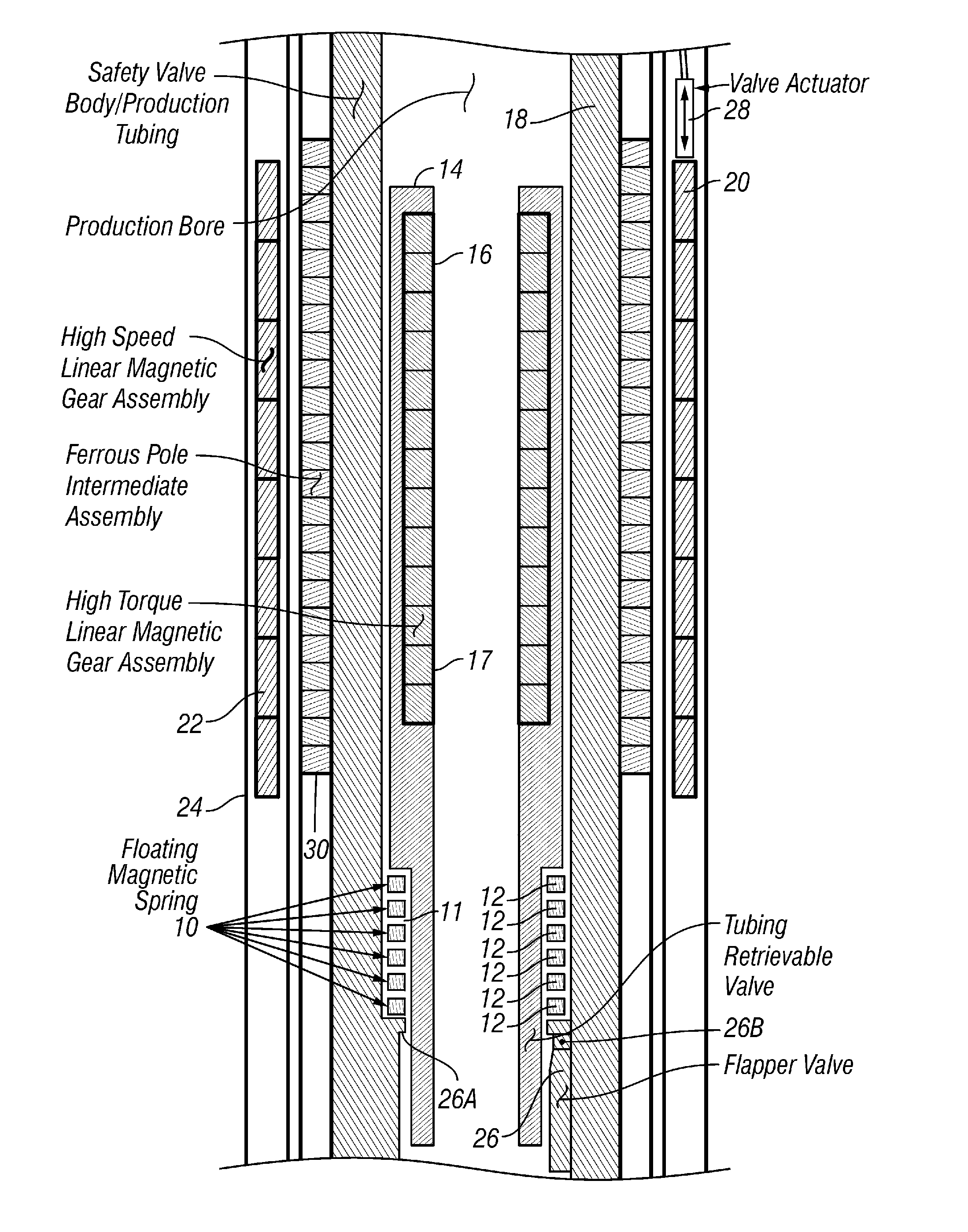
[0020]A wellbore valve such as a subsurface safety valve according to the various aspects of the invention may operate according to well known principles for such valves. See, e.g., U.S. Pat. No. 5,358,053 issued to Akkerman, which describes a subsurface safety valve having a particular metal spring structure. In embodiments of a subsurface safety valve according to the invention, an actuating mechanism that is arranged to open and close the valve may be magnetically coupled to a valve operator using a linear magnetic gear. Using a linear magnetic gear enables the use of a low-force, long stroke linear actuator to move a high-force short stroke valve actuator. The linear magnetic gear also eliminates the need to provide any seals between the actuator, valve operator and the moving components of the valve itself.
[0021]FIG. 1 shows a cross section of one embodiment of a subsurface safety valve assembly according to the various aspects of the invention. The safety valve assembly, which...
PUM
 Abstract
Description
Claims
Application Information