Valve actuator and method

a valve actuator and valve body technology, applied in the direction of valve operating means/releasing devices, service pipe systems, transportation and packaging, etc., can solve the problems of additional problems, unreasonably delay or preclude fail-safe operation, and limited hydraulic fluid volume and pressur

Inactive Publication Date: 2002-09-12
WORLDWIDE OILFIELD MACHINE INC
View PDF0 Cites 60 Cited by
  • Summary
  • Abstract
  • Description
  • Claims
  • Application Information

AI Technical Summary

Problems solved by technology

As water depth increases, increased hydrostatic head, or ambient sea pressure, creates forces on the valves and actuators that due to a combination of conditions can unreasonably delay or preclude fail-safe operation upon loss of hydraulic control pressure.
The valve size and internal valve line pressure can create additional problems under such conditions.
As well, the hydraulic fluid volume and pressure may be limited due to the need to avoid multiple hydraulic lines to the surface.
Moreover, it is sometimes desirable to change out hydraulic fluid to prevent contamination that might cause actuator failure.
Moreover, it would be desirable to avoid hydraulic fluid contact with return springs that are used in the subsea actuators because contaminants often eventually get into the hydraulic fluid and react with the return springs thereby further increasing hydraulic fluid contamination and / or damaging the return spring.
In some cases, such indicators require seals that may fail and cause actuator failure.
Indicators may also increase the size of the actuator.
The monolithic cap / hydraulic chamber is so limited in metal and machine time that it can be a throw away maintenance item.
While the above actuator has many advantages, the actuator uses a significant amount of hydraulic fluid which, as explained above can sometimes be problematic.
Contact of the spring with hydraulic fluid can also present a long term viability problem.
Moreover, the above patent does not address limiting the size of the actuator with respect to manual override operators and valve status indicators.
Furthermore, subsea actuators need to be very reliable because they operate in an environment that is not readily accessible.
Conventional subsea actuators often have numerous problems that limit the operational range, reliability, cost, and maintenance thereof.
While there are several commercially available subsea actuators on the market with different designs, the problems tend to be related.
For instance, over long periods of time packing may leak permitting flow of fluid between the actuator housing and valve bonnet.
This design is likely to cause hydraulic fluid contamination and spring damage.
Moreover, while this arrangement may afford sufficient spring strength for actuation to depths of 1000 feet or so, it results in numerous problems for deep water subsea actuators.
It is generally not desirable to increase the size of the hydraulic cylinder to provide a more powerful spring because this also increases the amount of hydraulic fluid necessary for operation and may present a potential problem at significant water depths.
With a limited spring size, the fail-safe operation that the spring may afford is limited because the spring size is quite limited.
Furthermore, positioning of the spring within the hydraulic cylinder also has the disadvantage of increasing the likelihood of ruining the sealing surfaces of the hydraulic cylinder due to contact with the spring during operation and also during assembly or disassembly.
The damage requires replacement or reworking of the entire actuator housing and is therefore quite expensive.
In this design, maintenance of even a single seal necessarily requires removal of the spring, which is normally under very high spring pressure, and may be a somewhat dangerous operation without special equipment.
Thus, even replacing a single seal is a time consuming, costly operation.
Not only is extensive time required for maintenance, but parts including additional replacement seals of all stationary metal-to-metal seals are necessary even though such may have been operating fine without problem.
Thus, commonly available actuators tend to have numerous limitations including highly limited operational abilities, reliability problems, and very high maintenance costs.

Method used


Image

  • Valve actuator and method
  • Valve actuator and method
  • Valve actuator and method

Examples


Embodiment Construction

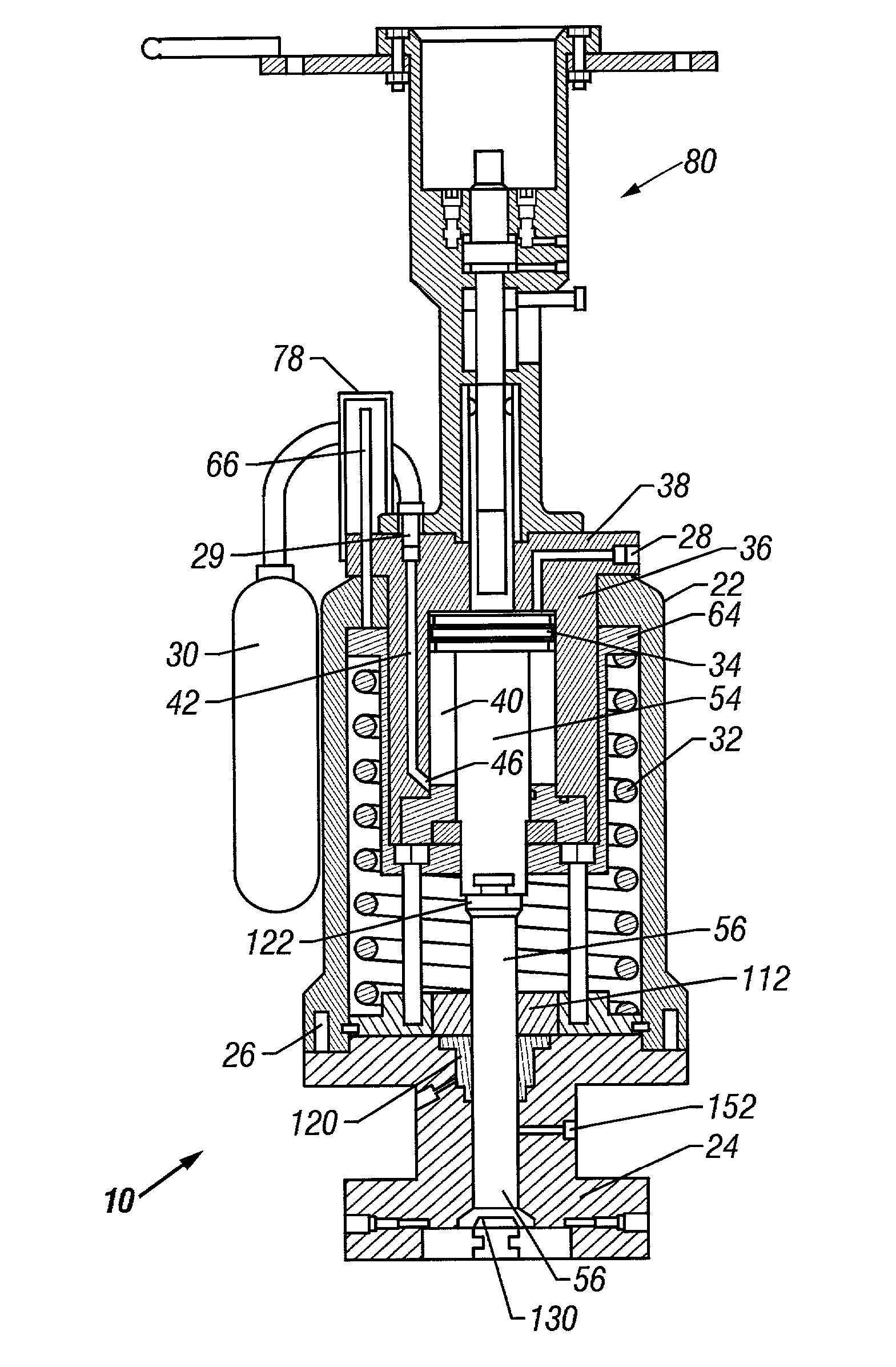
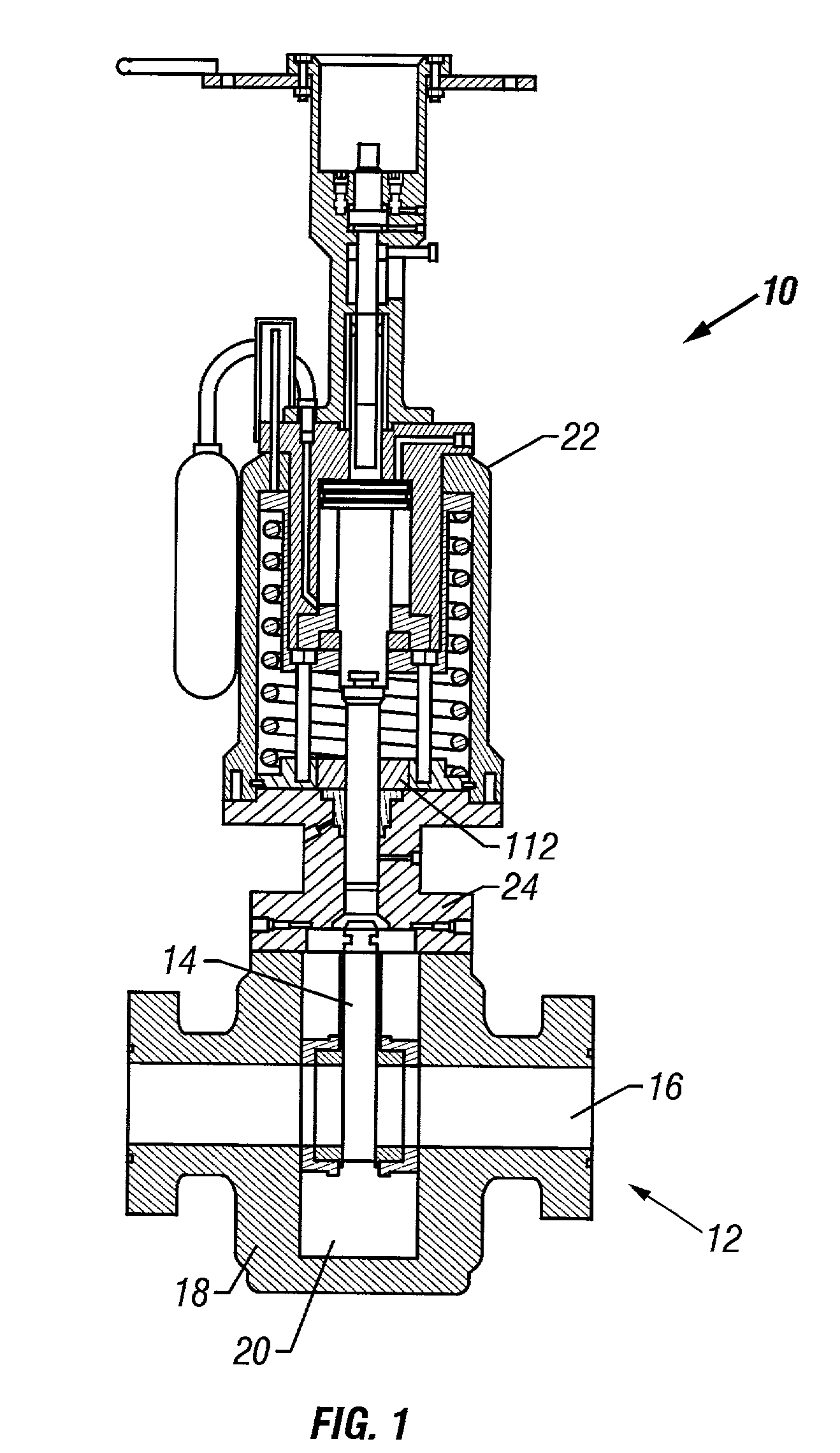
[0041] Referring now to the drawings, and more particularly to FIG. 1, the generally preferred configuration of subsea actuator 10, in accord with the present invention, is illustrated connected to gate valve 12. Various types of gate valves, such as gate valve 12 may be controlled using the actuator of the present invention. Gate valve 12 includes a gate 14 that may be moved between an open position and a closed position as is well known to control fluid flow through passageway or line 16. Gate valve 12 includes gate valve housing 18. Gate valve chamber 20 may be at line pressure sometimes during operation and one object of the present invention is to provide means for preventing leakage between gate valve chamber 20 and actuator housing 22 as is discussed hereinbelow in detail.

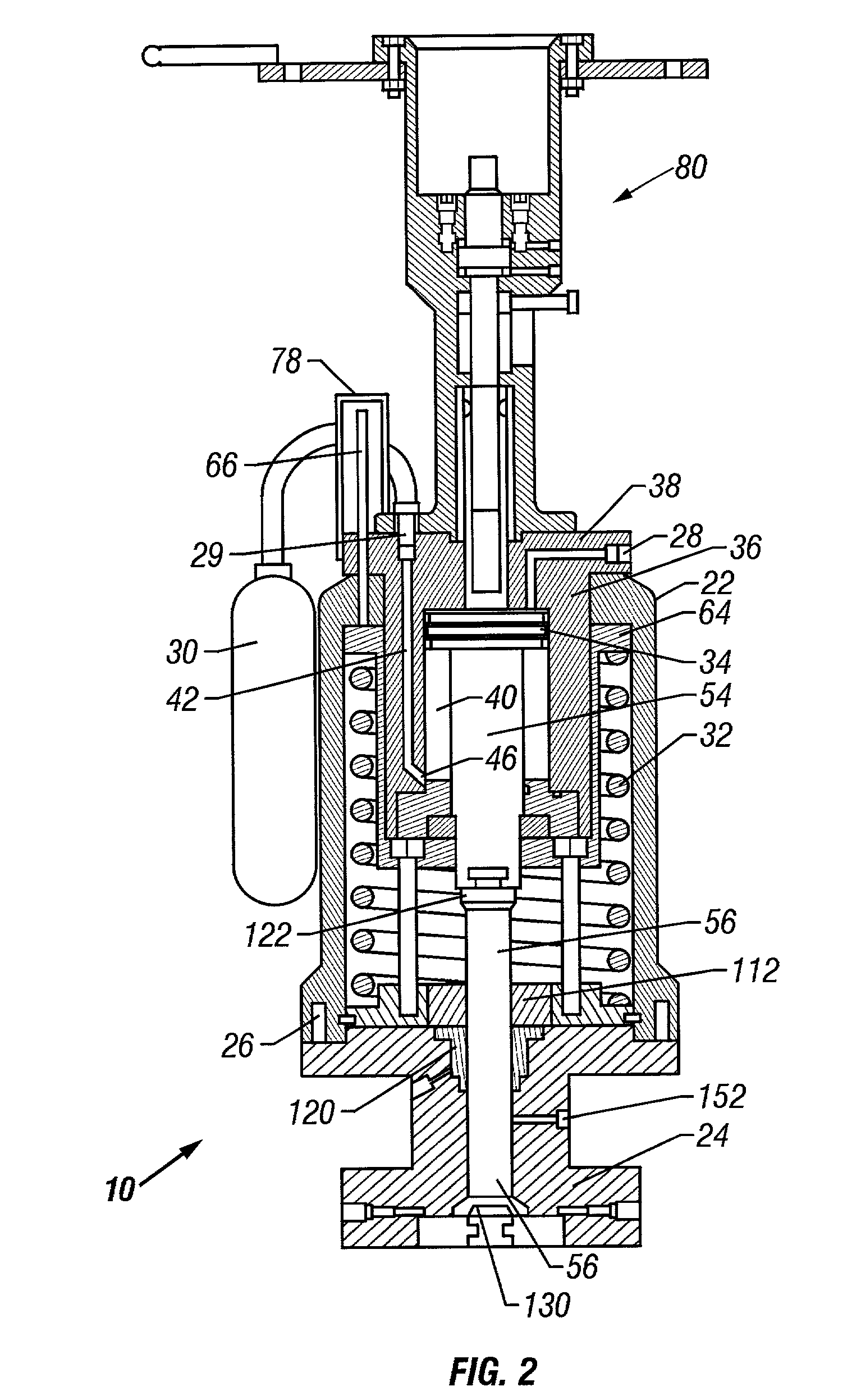
[0042] FIG. 2 shows actuator 10 in a somewhat enlarged view. Actuator housing 22 is removably connected to bonnet 24 preferably be means of bolts 26 although other removable fasteners, such as various types ...


PUM


Abstract

A subsea actuator and method is disclosed that includes all moving components mounted in a compact, concentric configuration. The subsea actuator is highly reliable and will operate at depth even with zero valve body cavity pressure. A preferably cup-shaped spring pusher is provided in telescoping relationship to the hydraulic chamber. A piston position indicator is provided which is connected externally to the hydraulic piston cylinder to avoid the possibility of hydraulic leaks due to the piston indicator. A manual override may be provided with a manual override indicator. The manual override indicator has a shorter travel length than the manual override operating stem to thereby reduce the overall length of the manual override assembly. The driving stem provides a removable connection to the hydraulic piston from the top of the actuator housing and a quick disconnect permits disconnection of the driving stem from the valve stem. In a preferred embodiment, upper and lower t-slot connections are utilized in the driving stem assembly. In a preferred embodiment, two back seat valves are removably secured to the driving stem to engage respective seats and provide additional sealing around the driving stem so as to prevent leakage between the valve chamber and actuator housing chamber. The high tension spring does not need to be removed to perform maintenance, and all wear items and seals are readily accessible. Change or replacement of the stem packing is made from the top of the bonnet to avoid dissasembling the bonnet to valve body connection. Pre-load bolts are used to adjustably preload the tension in the return spring. The height/weight of the actuator is significantly reduced as compared to prior art subsea valve actuators.

Description

[0001] 1. Field of the Invention[0002] The present invention relates generally to gate valve actuators and, in a particular embodiment, to apparatus and methods for a fail-safe hydraulic subsea actuator that reliably operates in deep water for extended time periods.[0003] 2. Description of the Background[0004] Remote subsea fail-safe gate valves are typically controlled with hydraulic actuators The hydraulic actuators and often their controls are located on the ocean floor along with other equipment. Due to the cost of positioning equipment on the ocean floor, it is desirable that any equipment be as compact as possible while still affording very high reliability. Although the location, configuration and types of actuators and controls vary, their operation is subjected to ambient sea pressure whether the actuator and controls are an open or closed system. The time required for a fail-safe valve to fail-safe close is critical, and therefore a short response time is highly desirable....

Claims


Application Information

Patent Timeline
Patent Type & Authority Applications(United States)
IPC IPC(8): F16K31/122F16K37/00
CPCF16K31/122F16K37/0008Y10T137/0396Y10T137/0497Y10T137/402Y10T137/8158Y10T137/8175Y10T137/8275Y10T137/8359
Inventor SUNDARARAJAN, ALAGARSAMY
Owner WORLDWIDE OILFIELD MACHINE INC
Why Eureka
Try Eureka