Resetting an electronic ballast in the event of fault

Active Publication Date: 2010-12-02
OSRAM SYLVANIA INC
View PDF8 Cites 345 Cited by
  • Summary
  • Abstract
  • Description
  • Claims
  • Application Information

AI Technical Summary

Benefits of technology

[0004]Aspects of the invention include a ballast for driving a lamp. In one embodiment, a rectifier connected to a power source is configured to receive electricity from the power source. The rectifier generates a DC bus voltage upon receiving electricity. A driver circuit is configured to receive the DC bus voltage from the rectifier and to generate a lamp voltage to drive the lamp upon receiving the DC bus voltage. A controller is configured to control the driver circuit, monitor a first value corresponding to the DC bus voltage, and additionally monitor a second value corresponding to the lamp voltage. The controller disables the dri

Problems solved by technology

Faults can disrupt ballast operation.
For example, a momentary power interruption, such as

Method used


Image

  • Resetting an electronic ballast in the event of fault
  • Resetting an electronic ballast in the event of fault
  • Resetting an electronic ballast in the event of fault

Examples


Embodiment Construction

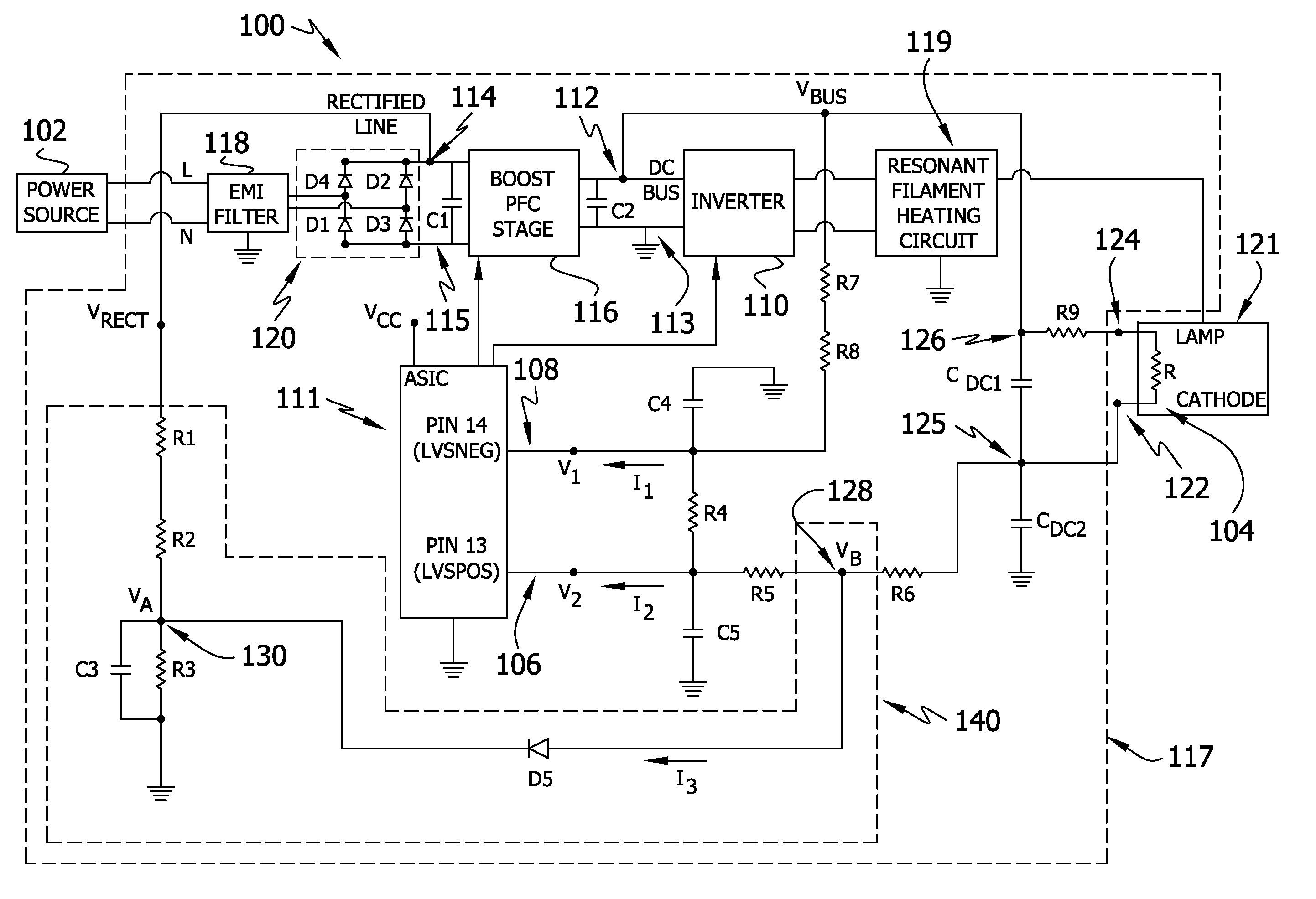
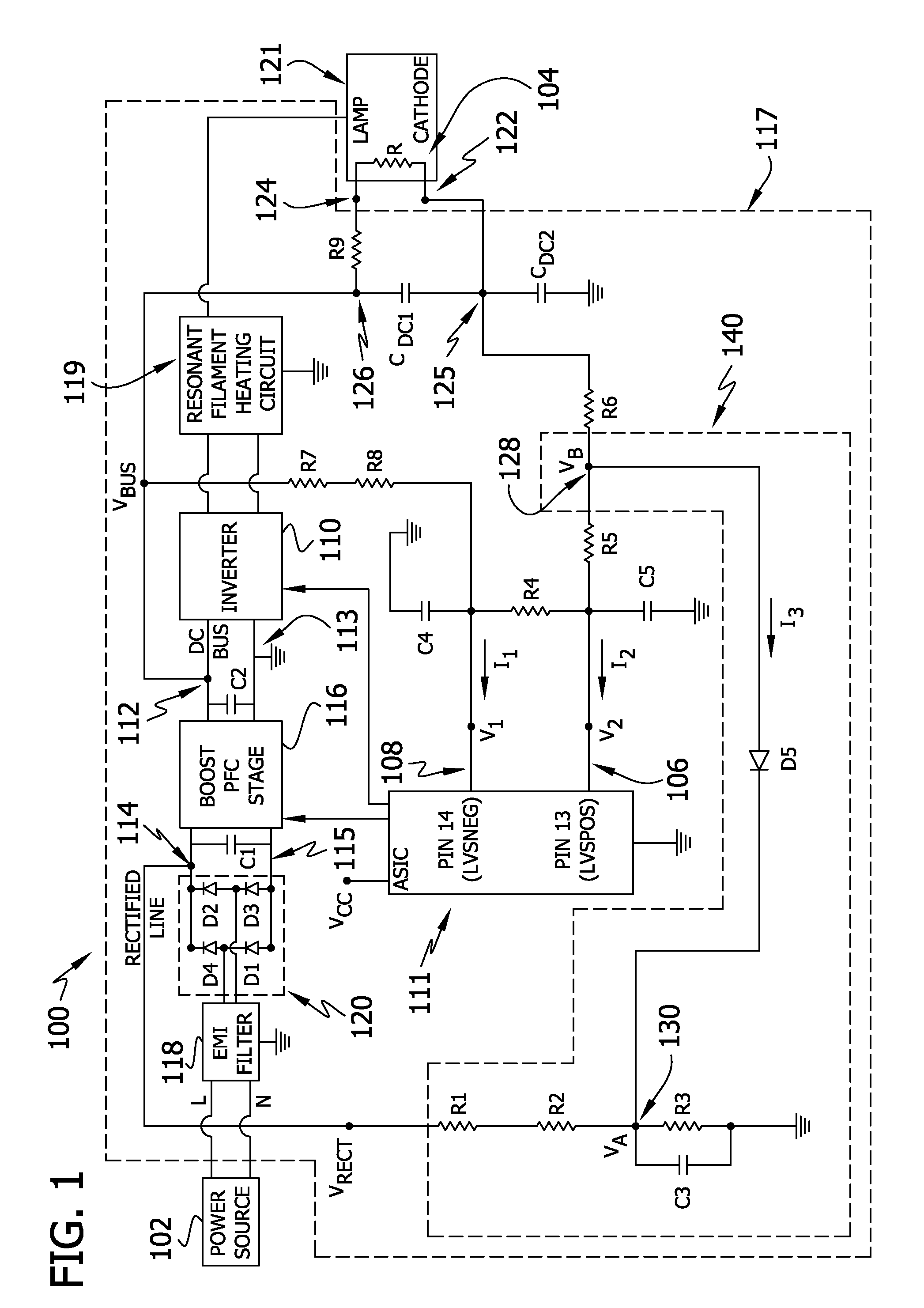
[0013]Embodiments of the invention include a ballast 100 for driving a lamp 121. A rectifier 120 connected to a power source 102 is configured to receive electricity from the power source 102 and to generate a DC bus voltage Vbus upon receiving electricity. A driver circuit 117 is configured to receive the DC bus voltage from the rectifier 120 and generate a lamp voltage Vb to drive the lamp 121 upon receiving the DC bus voltage Vbus. The driver circuit 117 is controlled by a controller 111 that monitors a first value 108 corresponding to the DC bus voltage Vbus, and a second value 106 corresponding to the lamp voltage Vb.

[0014]In normal operation, the controller 111 resets after a preset period of time after the controller 111 detects a fault condition. A fault condition occurs when a component of the lamp ballast 100 does not behave in an expected manner for any reason. Thus, a fault condition may occur when a component of the lamp ballast 100 suffers a total failure (e.g., the co...


PUM


Abstract

A ballast for driving one or more lamps includes a controller and a current reduction circuit for accelerating a controller reset. Upon detecting a fault, the controller disables the ballast for a preset period of time, and resets. The controller additionally resets when the ratio of a supplied second value to a supplied first value falls below a threshold value. The current reduction circuit reduces the supplied second value in less than the preset period of time, such that the ratio falls below the threshold value and the controller resets. An emergency lighting system includes the ballast as a primary ballast, a backup ballast, and a primary power source. The controller detects a fault if the primary power source de-energizes and the backup ballast disconnects the one or more lamps from the primary ballast. The current reduction circuit accelerates the reset of the controller when the primary power source de-energizes.

Description

CROSS-REFERENCE TO RELATED APPLICATIONS[0001]Co-invented and co-owned U.S. patent application Ser. No. ______, filed simultaneously herewith, entitled Electronic Ballast Control Circuit, is incorporated herein by reference in its entirety. In addition, co-invented and co-owned U.S. patent application Ser. No. ______, filed simultaneously herewith, entitled Relamping Circuit for Dual Lamp Electronic Ballast, is incorporated herein by reference in its entirety.FIELD OF THE INVENTION[0002]The invention generally relates to electronic ballasts for providing power to one or more lamps. More particularly, the invention is concerned with quickly restarting the ballast in response to a power toggle.BACKGROUND OF THE INVENTION[0003]Ballasts provide power to one or more lamps and regulate the current, voltage, and / or power provided to the lamps. The ballast often contains one or more controllers, integrated circuits and other active and passive components to regulate the power provided to the...

Claims


Application Information

Patent Timeline
IPC IPC(8): H05B37/02
CPCH05B41/2981H05B37/04H05B47/29
Inventor BAKRE, SHASHANKKUMAR, NITIN
Owner OSRAM SYLVANIA INC
Why Eureka
Try Eureka