

Field winding type generator-motor
a generator-motor and field winding technology, applied in the direction of electric generator control, electric generator control, dynamo-electric converter control, etc., can solve the problems of conventional technique, generator-motor for vehicle out of order, high operating temperature of generator-motor for vehicle, etc., to minimize cost increase and structure modification, the effect of preventing a failur
- Summary
- Abstract
- Description
- Claims
- Application Information
AI Technical Summary
Benefits of technology
Problems solved by technology
Method used
Image

Examples
embodiment 1
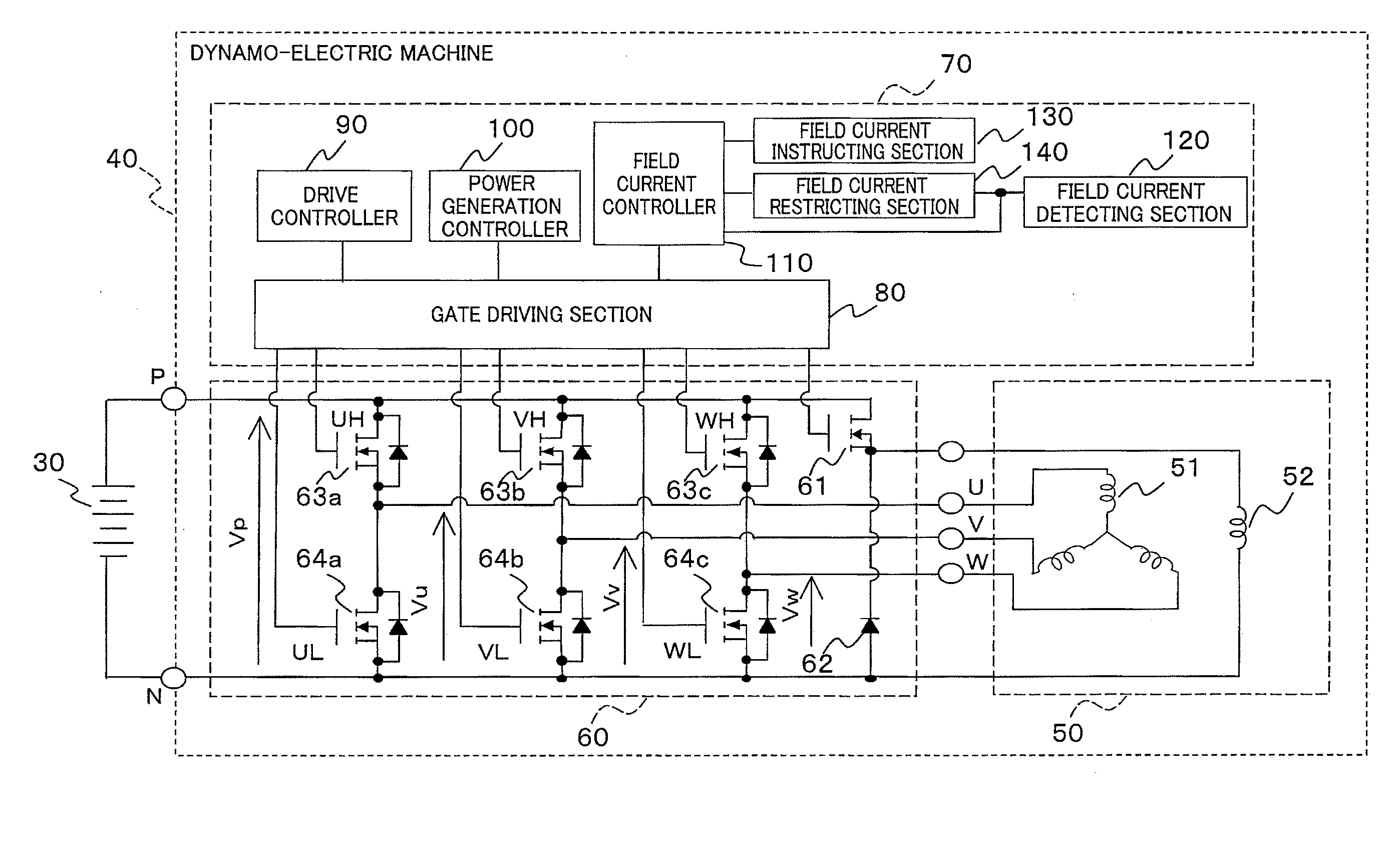
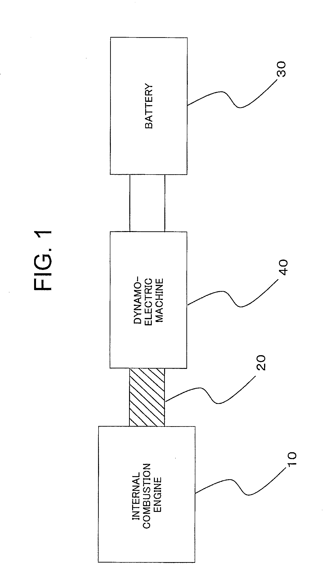
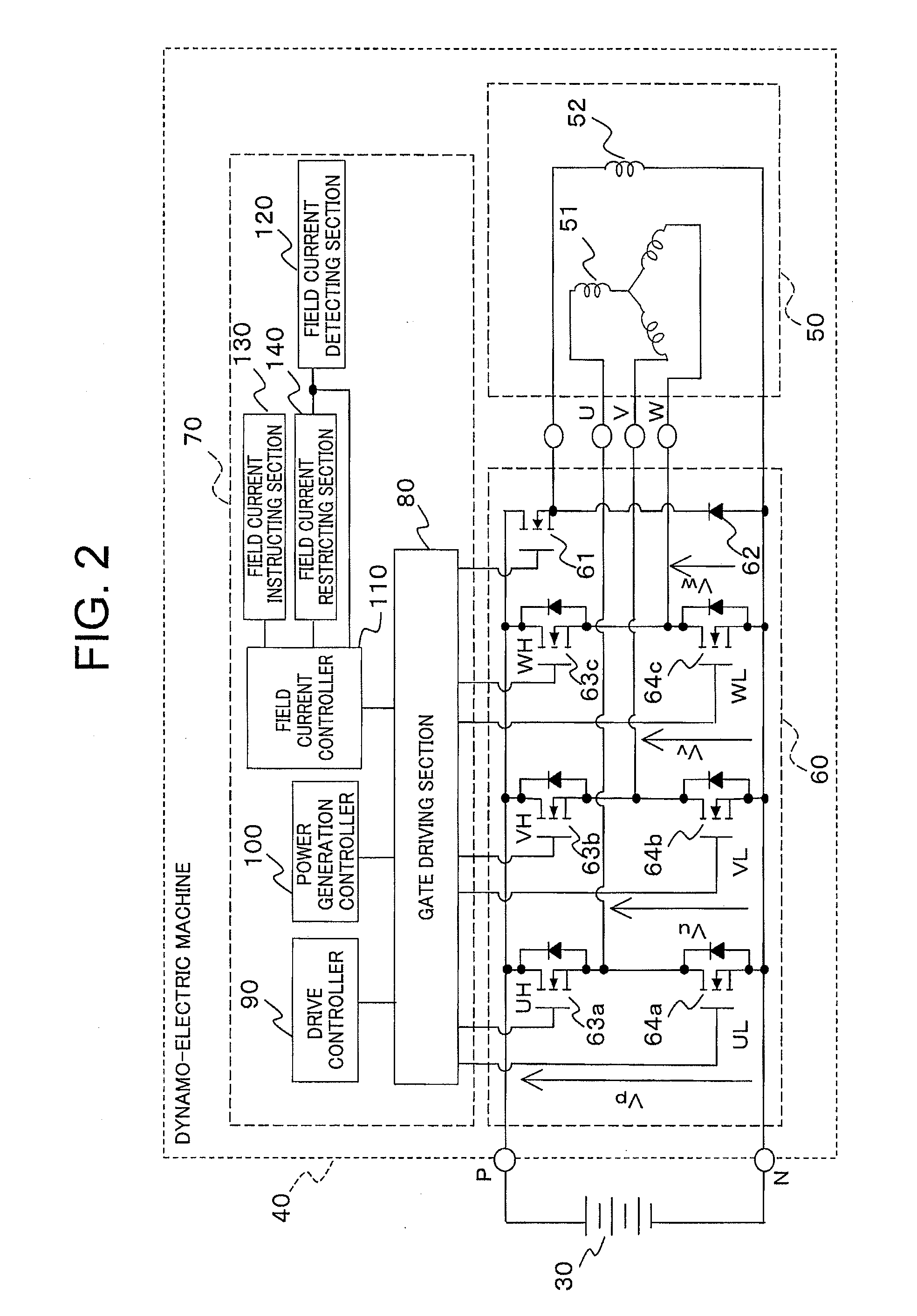
[0022]FIG. 1 is a block diagram of a case where a field winding type generator-motor according to Embodiment 1 of the present invention is mounted on a vehicle. The field winding type generator-motor of FIG. 1 is equipped with an internal combustion engine 10, a coupling means 20, a battery 30, and a dynamo-electric machine 40.
[0023]The internal combustion engine 10 and the dynamo-electric machine 40 are coupled to each other via the coupling means 20. The battery 30 and the dynamo-electric machine 40 are electrically connected to each other. Here, examples of the coupling means 20 include a belt and a pulley.
[0024]Note that the internal combustion engine 10 and the dynamo-electric machine 40 are coupled via the coupling means 20 in Embodiment 1 of the present invention, however, the structure is not limited thereto, and the internal combustion engine 10 and the dynamo-electric machine 40 maybe directly coupled to each other.
[0025]In addition, the internal combustion engine 10 is no...
embodiment 2
[0050]In the above description of Embodiment 1, the field current restriction is performed when the detected field current is larger than the predetermined field current threshold value for the predetermined permitted time. In contrast, in Embodiment 2 of the present invention that is described below, the field current restriction is performed based on a time integral value of the field current value that is larger than a predetermined field current threshold value.
[0051]FIG. 5 is an internal block diagram of a field current restricting section 140 according to Embodiment 2 of the present invention. The field current restricting section 140 in FIG. 5 includes a storing section 141, a field current restriction deciding section 142, and a field current restriction instructing section 143.
[0052]The storing section 141 includes a field current threshold value storing section 141a, a field current restriction value storing section 141c, a field current restriction time storing section 14...
embodiment 3
[0059]In Embodiments 1 and 2 described above, the single field current threshold value is used for deciding whether or not the restriction on the field current is necessary. In contrast, according to Embodiment 3, a description is given of a case where two field current threshold values are used for deciding whether or not the restriction on the field current is necessary.
[0060]FIG. 7 is an internal block diagram of a field current restricting section 140 according to Embodiment 3 of the present invention. The field current restricting section 140 of FIG. 7 includes a storing section 141, a field current restriction deciding section 142, and a field current restriction instructing section 143.
[0061]The storing section 141 includes a field current threshold value storing section 141a, a field current restriction value storing section 141c, a field current restriction time storing section 141d, and a field current integral threshold value storing section 141e. In addition, the field c...
PUM
 Abstract
Description
Claims
Application Information