Ship hull air microbubble lubrication system

a lubrication system and microbubble technology, applied in watercraft hull design, hulls, vessel construction, etc., can solve the problems of ballast water mainline modification to connect to venturi, wear on ballast water pumps, etc., to reduce frictional drag, reduce frictional drag on hull, and minimize ship structure modifications

Inactive Publication Date: 2022-01-20
KHREIBANI JAMES
View PDF0 Cites 0 Cited by
  • Summary
  • Abstract
  • Description
  • Claims
  • Application Information

AI Technical Summary

Benefits of technology

[0006]Generally stated this disclosure relates to a ship hull microbubble system used to reduce frictional drag on a ship hull while traveling through water. The disclosure includes a pump which discharges motive fluid to power an ejector which intern draws and compresses air within the ejector mixing throat. As the low pressure air enters the ejector throat it is compressed by the relatively high pressure liquid motive and becomes entrained within the liquid as microbubbles. The microbubble liquid multiphase fluid then exits the ejector where it is discharged into the ship boundary layer through dedicated hull openings located below the waterline and within the ship hull structure. The discharged ejector microbubble fluid then creates a plurality of microbubbles within the ships boundary layer reducing the frictional drag on the hull. This disclosure has advantages when compared to related art through minimizing ship structure modifications, reducing wear on the ballast pump, operational autonomy from the ballast system, reducing the systems area footprint, independent control of the air injection rate, simplified installation through reducing existing pipework modifications and removing the need for riser pipes and additional tanks.

Problems solved by technology

The specific need for a ballast pump will require the ballast water mainline to be modified to connect to the venturi which may be difficult depending on the location and distance the ballast water mainline is from both the venturi and microbubble discharge point on the ships hull.
Additional issues include wear on the ballast water pump from continual operation required to create microbubbles where the ship ballast system is normally used infrequently while ballasting.

Method used


Image

  • Ship hull air microbubble lubrication system
  • Ship hull air microbubble lubrication system

Examples


Embodiment Construction

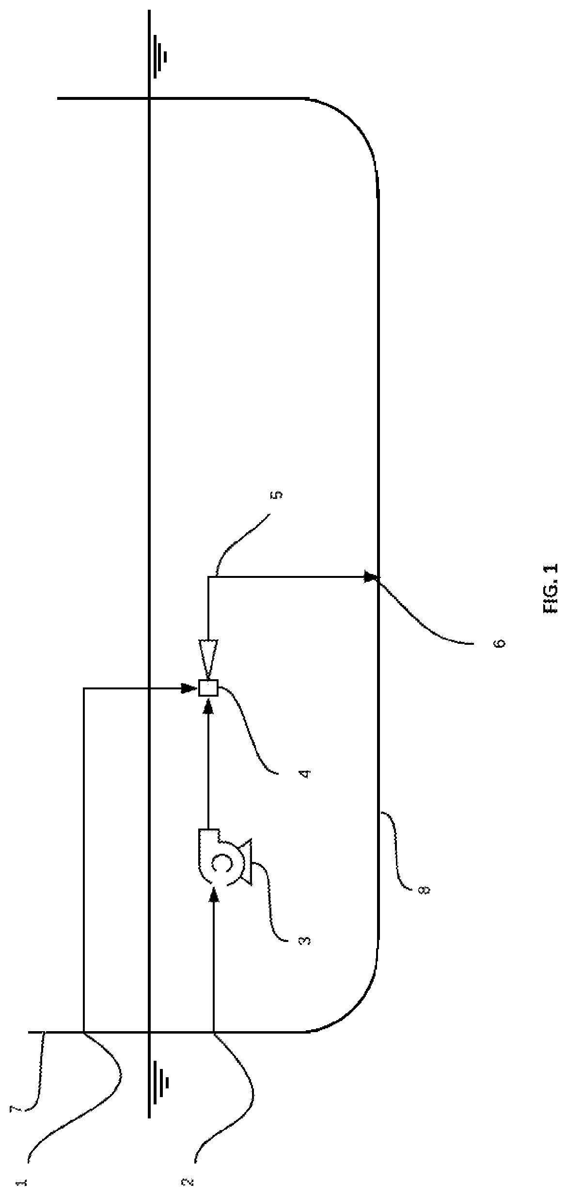
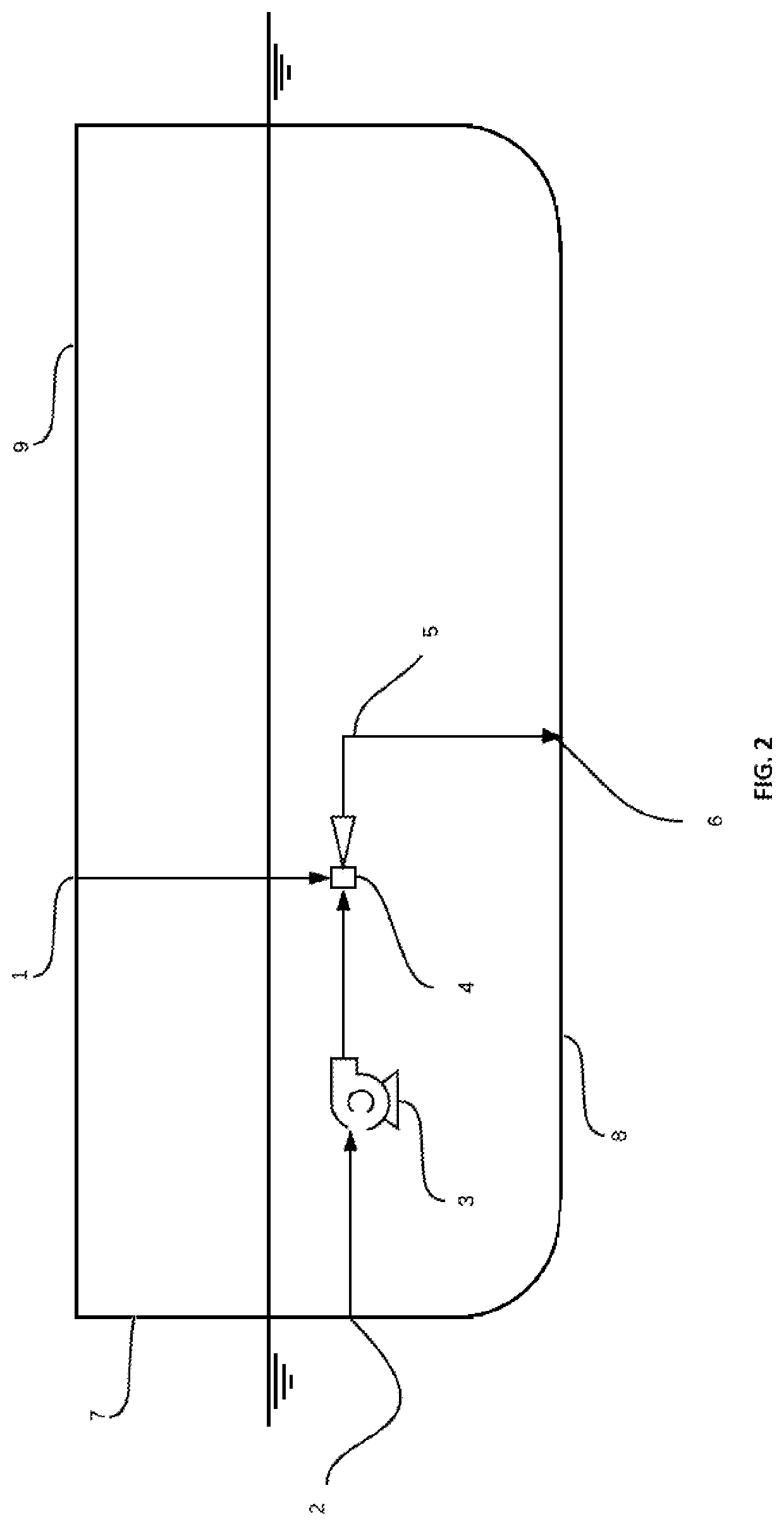
[0027]By way of example, and referring to FIG. 1, one embodiment of the disclosure comprises a ejector air intake (1) penetrating the side of the ship hull (7) above the waterline and mechanically coupled to a ejector (4). The term “mechanically coupled” may include by way of example and without limitation, combined into a single component during the original equipment manufacturers (OEM) process, pipework, ducting, flanges, fasteners and any combination of mechanically coupled devices that convey air or water. The term “ejector” refers to any device utilizing venturi principles to create air microbubbles within water for example and without limitation educator and jet pump. The ejector water intake (2) penetrates the ship hull side (7) or ship hull bottom (8) below the waterline and mechanically coupled to a pump (3). The pump (3) is mechanically coupled to the ejector (4) where the pump (3) pressurizes the water from the ejector water intake (2) and causes the ejector (4) to draw ...


PUM


Abstract

This disclosure relates to a ship hull microbubble system used to reduce frictional drag on a ship hull while traveling through water. The microbubble system includes a water pump connected to an ejector which intern draws and compresses air within the ejector body. While in the ejector the compressed air becomes entrained within the pumped liquid as microbubbles creating a multiphase fluid which is then ejected at suitable pressure from the ship hull below the waterline through dedicated hull openings. The ejected air liquid multiphase fluid then creates plurality of microbubbles within the below water boundary layer reducing frictional drag generated by the hull as it travels through water. This disclosure has advantages when compared to related art through minimizing ship structure modifications, reducing wear on the ballast pump, operational autonomy from the ballast system, reducing the systems area footprint, independent control of the air injection rate, simplifying the installation through reducing existing pipework modifications and removing the need for riser pipes and additional tanks.

Description

CROSS-REFERENCE TO RELATED APPLICATIONS[0001]This application claims the benefit of provisional patent application Ser. No. 62 / 675,722, filed 15 Jul. 2019 by the present inventor.FIELD OF THE INVENTION[0002]This disclosure relates to a microbubble system used to reduce drag on a ship hull while traveling through water. The microbubble system includes a pump which discharges motive water through an ejector. The ejector then draws and compresses air within the throat and discharges air microbubbles entrained within the motive water creating a multiphase fluid. This microbubble fluid is discharged from the ship hull through dedicated hull openings located within the ship hull structure and below the waterline. The discharged fluid creates a plurality of microbubbles around the ship hull and reduce the density within the ships boundary layer therefore drag.BACKGROUND OF THE INVENTION[0003]The following is a tabulation of related art that presently appears relevant:U.S. PatentsPat. No.Ki...

Claims


Application Information

Patent Timeline
Patent Type & Authority Applications(United States)
IPC IPC(8): B63B1/38
CPCB63B1/38B63B2001/387Y02T70/10
Inventor KHREIBANI, JAMES
Owner KHREIBANI JAMES
Why Eureka
Try Eureka