Tractor with improved valve system

a valve system and tractor technology, applied in the field of tractors, can solve the problems of not being able to extend the distance being unable to bring back rotary equipment at the surface, and being unable to achieve the extended distance of the borehole without the aid of a tractor, so as to limit the design life of the tractor and/or other attached tools, and limit the operation range and efficiency of the tractor.

Inactive Publication Date: 2010-12-09
WWT NORTH AMERICA HLDG
View PDF99 Cites 15 Cited by
  • Summary
  • Abstract
  • Description
  • Claims
  • Application Information

AI Technical Summary

Benefits of technology

[0048]Furthermore, the inventors have found that the large pressure cycles add undesirable fatigue cycles to the internal tractor components and / or to the attached tools. This may limit the design life of the tractor and / or other attached tools and can thereby significantly impact the operating cost of using the tractor.
[0049]Still further, the inventors have found that pressure-actuated valves may be susceptible to premature shifting due to pressure spikes or other large fluid pressure fluctuations. Similarly, testing has shown that the valves may be particularly susceptible to premature shifting when the tractor system is subjected to heavy loads, and / or large dynamic pressure waves (or “water hammer” effects) caused by the opening and closing of other valves within the control assembly. In certain applications, premature valve shifting may significantly limit the operational range and efficiency of the tractor.
[0050]In various embodiments of the present invention, there is provided an improved valve system adapted for use with a tractor that overcomes the above-mentioned problems of the prior art. These embodiments represent a major advancement in the art of tractors, and particular in the art of well intervention tools. Compared to the prior art, certain embodiments of the improved valve system can provide for greater control of tractor movement and operate very effectively within a much larger zone of parameters. In addition, by providing for better control over the fluid pressure, certain embodiments of the improved valve system can extend the useful life of internal components and thereby reduce operating costs.
[0051]In one aspect, a tractor for moving a component through a borehole comprises an elongate body with aft and forward gripper assemblies longitudinally movably engaged thereon. The aft and forward gripper assemblies are preferably hydraulically actuated for selectively engaging an inner surface of the borehole. Aft and forward propulsion assemblies are provided for advancing the body through the borehole relative to the aft and forward gripper assemblies, respectively. A gripper control valve is provided for directing pressurized fluid to the aft and forward gripper assemblies. The gripper control valve preferably has a first position for directing pressurized fluid to the aft gripper assembly and a second position for directing pressurized fluid to the forward gripper assembly. In a significant feature, aft and forward mechanically actuated valves disposed along the body for detecting advancement of the body relative to said aft or forward gripper assembly, respectively, thereby providing a mechanism for improving the timing and efficiency of the tractor operation. In particular, the aft and forward mechanically actuated valves are in fluid communication with the gripper control valve for causing the gripper control valve to change positions after the body has completed an advancement stroke through the borehole relative to said aft or forward gripper assembly.

Problems solved by technology

As the drill string is lowered or raised within the borehole, it is necessary to continually add or remove links of drill pipe at the surface, at significant time and cost.
It is more expensive to bring back the rotary equipment than it is to bring in a coiled tubing unit.
However, in many situations, the coiled tubing unit may not be capable of reaching extended distances within the borehole without the aid of a tractor.

Method used


Image

  • Tractor with improved valve system
  • Tractor with improved valve system
  • Tractor with improved valve system

Examples


Embodiment Construction

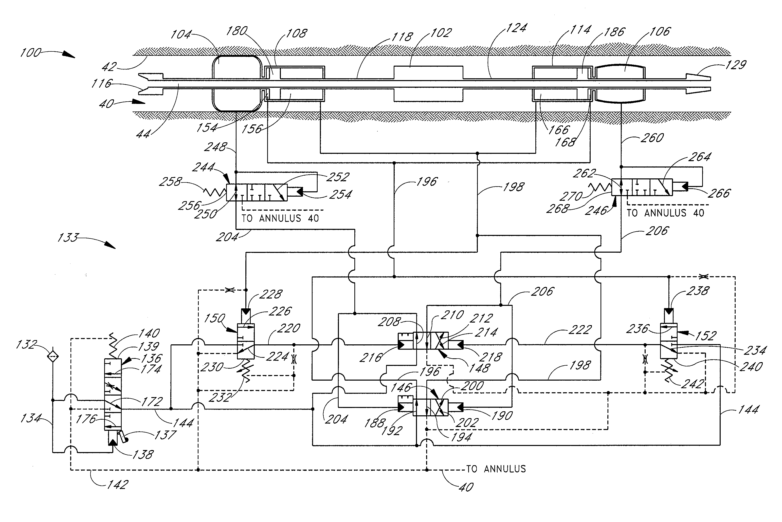
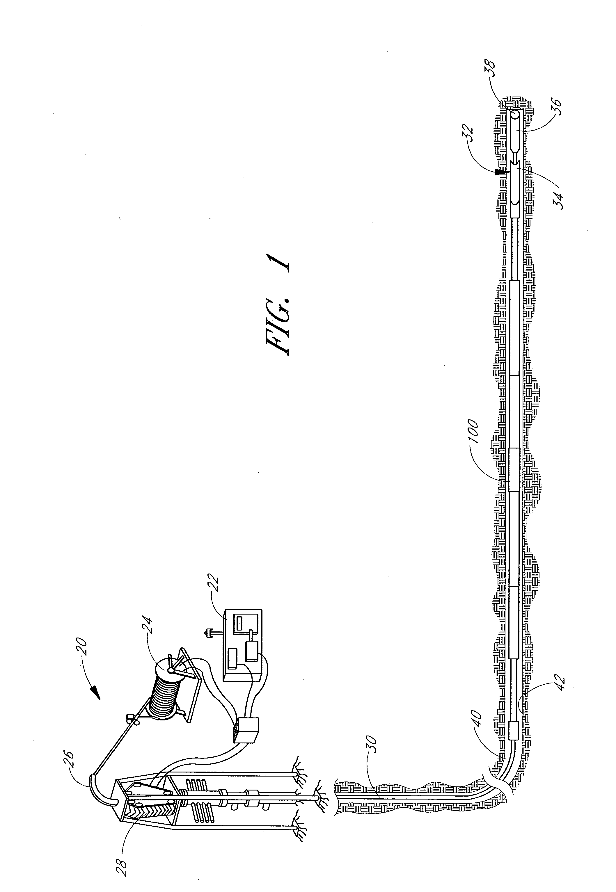
[0110]FIG. 1 shows a hydraulic tractor 100 for moving equipment within a passage, configured in accordance with a preferred embodiment of the present invention. In the embodiments shown in the accompanying figures, the tractor of the present invention may be used in conjunction with a coiled tubing drilling system 20 and adjoining downhole equipment 32. The system 20 may include a power supply 22, tubing reel 24, tubing guide 26, tubing injector 28, and coiled tubing 30, all of which are well known in the art. The tractor 100 is configured to move within a borehole having an inner surface 42. An annulus 40 is defined by the space between the tractor 100 and the inner surface 42 of the borehole.

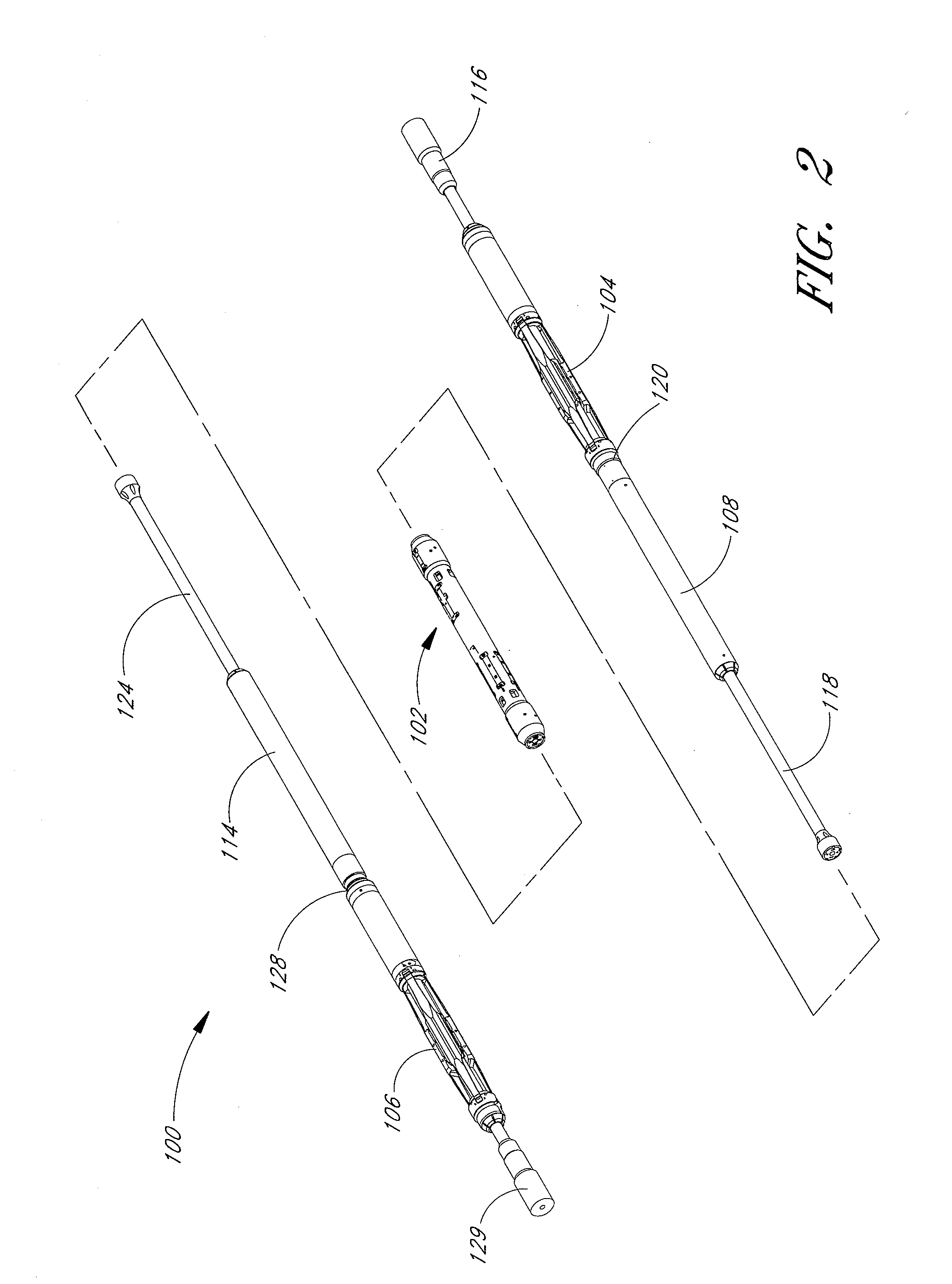
[0111]The downhole equipment 32 may include various types of equipment that the tractor 100 is designed to move within the passage. For example, the equipment 32 may comprise a perforation gun assembly, an acidizing assembly, a sandwashing assembly, a bore plug setting assembly, an E-line, a l...


PUM


Abstract

A hydraulically powered tractor adapted for advancement through a borehole including an elongate body, aft and forward gripper assemblies, and a valve control assembly housed within the elongate body. The aft and forward gripper assemblies are adapted for selective engagement with the inner surface of the borehole. The valve control assembly includes a gripper control valve for directing pressurized fluid to the aft and forward gripper assemblies. The valve control assembly also includes a propulsion control valve for directing fluid to an aft or forward power chamber for advancing the body relative to the actuated gripper assembly. Aft and forward mechanically actuated valves may be provided for controlling the position of the gripper control valve by detecting and signaling when the body has completed an advancement stroke relative to an actuated gripper assembly. Aft and forward sequence valves may be provided for controlling the propulsion control valve by detecting when the gripper assemblies become fully actuated. Furthermore, a pressure relief valve is preferably provided along an input supply line for limiting the pressure of the fluid entering the valve control assembly.

Description

CLAIM FOR PRIORITY[0001]This application is a continuation-in-part of and claims priority to co-pending U.S. application Ser. No. 12 / 606,986, filed Oct. 27, 2009, which is a continuation of U.S. application Ser. No. 12 / 046,283, filed Mar. 11, 2008, now U.S. Pat. No. 7,607,495, which is a continuation of U.S. application Ser. No. 11 / 717,467, filed Mar. 12, 2007, now U.S. Pat. No. 7,353,886, which is a continuation of U.S. application Ser. No. 11 / 418,546, filed May 3, 2006, now U.S. Pat. No. 7,188,681, which is a continuation of U.S. patent application Ser. No. 10 / 759,664, filed Jan. 19, 2004, now U.S. Pat. No. 7,080,700, which is a continuation of U.S. application Ser. No. 10 / 004,965, filed Dec. 3, 2001, now U.S. Pat. No. 6,679,341, which claims the benefit under 35 U.S.C. §119(e) of U.S. Provisional Patent Application Ser. No. 60 / 250,847, filed Dec. 1, 2000.[0002]This application is also a continuation-in-part of and claims priority to co-pending U.S. application Ser. No. 12 / 368,417...

Claims


Application Information

Patent Timeline
Patent Type & Authority Applications(United States)
IPC IPC(8): E21B4/00
CPCE21B4/18E21B2023/008E21B23/04E21B23/001E21B23/042E21B23/0413
Inventor MOCK, PHILIP W.KRUEGER, V, RUDOLPH ERNSTBLOOM, DUANEMOORE, N. BRUCELEVAY, ROBERT
Owner WWT NORTH AMERICA HLDG
Why Eureka
Try Eureka