Flapping apparatus with large flapping angles

Inactive Publication Date: 2010-12-09
KONKUK UNIV IND COOP CORP
View PDF9 Cites 32 Cited by
  • Summary
  • Abstract
  • Description
  • Claims
  • Application Information

AI Technical Summary

Benefits of technology

[0009]Accordingly, the present invention has been made keeping in mind the above problems occurring in the prior art, and an object of the present invention is to provide a flapping apparatus which is installed in a micro ornithopter

Problems solved by technology

An ornithopter with an engine has large output but is very noisy.
In addition, it is not easy for a beginner to handle the engine and the fuel.
In the case of a rubber band powered ornithopter or a compressed gas powered ornithopter, it is easy to handle the ornithopter but the flying time is relatively short and a user c

Method used


Image

  • Flapping apparatus with large flapping angles
  • Flapping apparatus with large flapping angles
  • Flapping apparatus with large flapping angles

Examples


Embodiment Construction

[0020]To reduce the size of a micro ornithopter, not only the size and weight of a fuselage but also the size of the wings must be reduced. However, the reduction in the size of the wings reduces the dynamic lift that allows the micro ornithopter to rise. Therefore, the flapping angles of the wings must be increased and the frequency of flapping must also be relatively high to ensure sufficient dynamic lift, to compensate for the wing size reduction.

[0021]The flapping principle of a beetle can be used as reference data to design such a micro ornithopter. The beetle has a flapping angle of about 160° and a flapping frequency of about 30 Hz when flying.

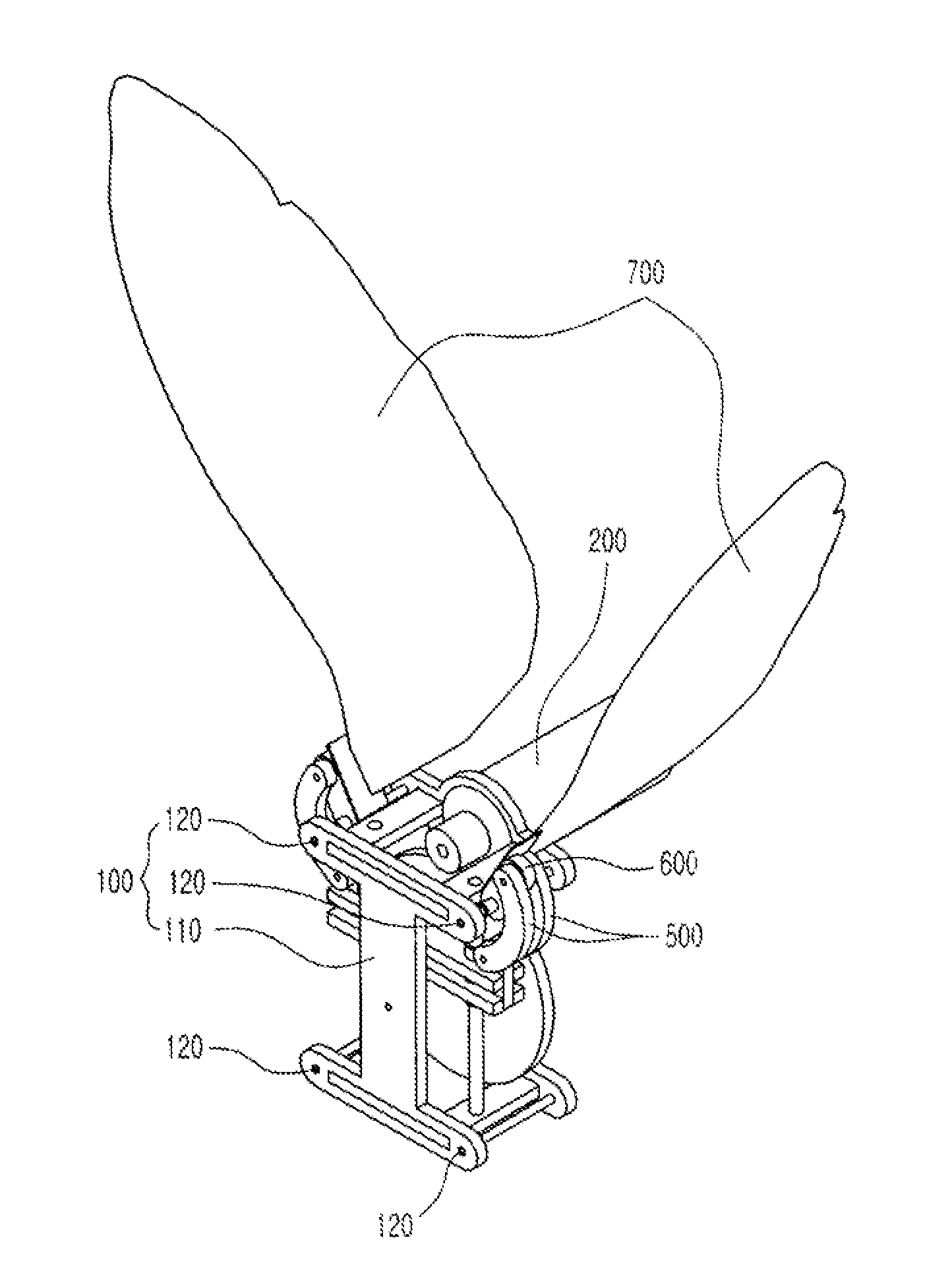
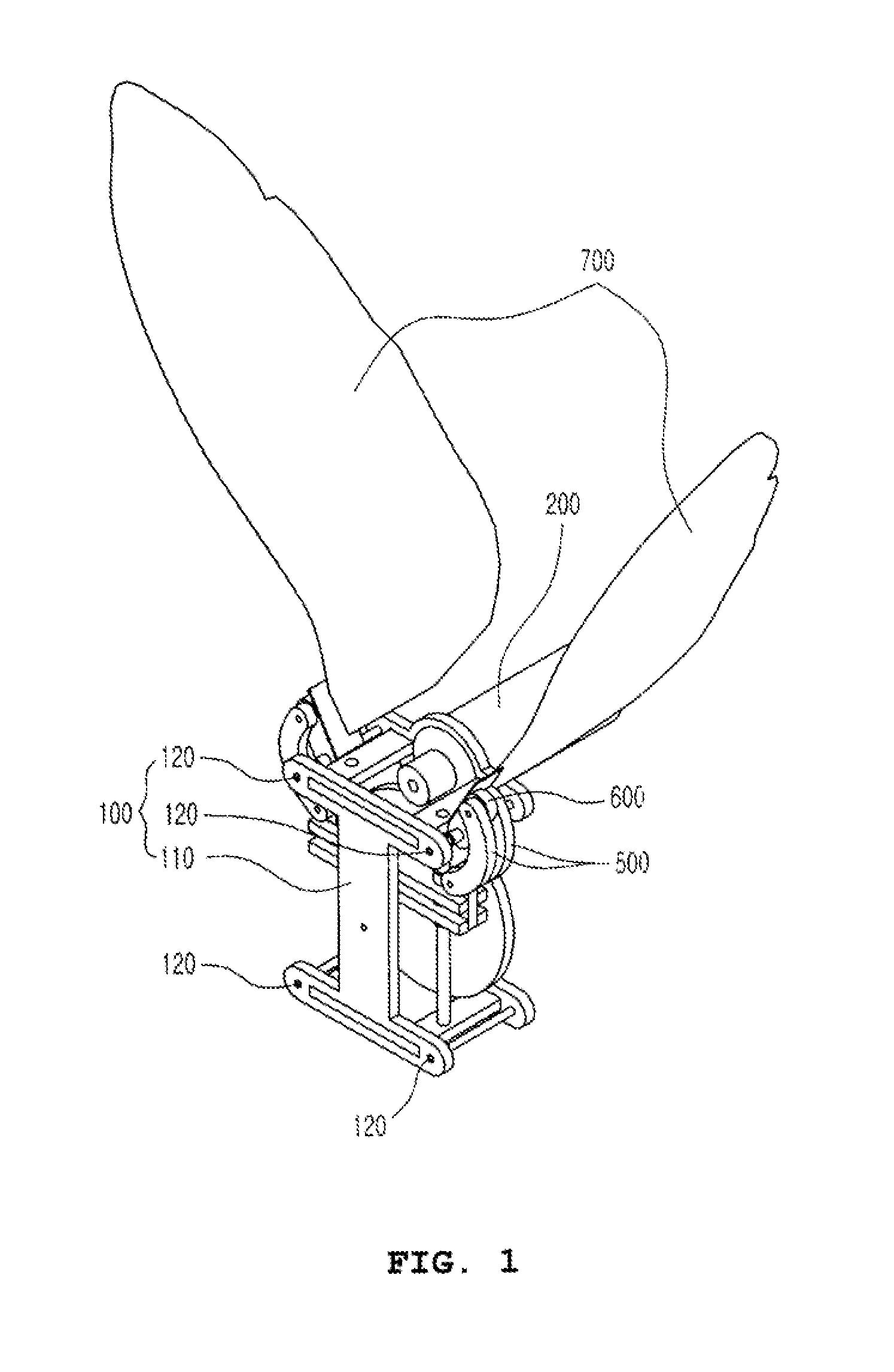
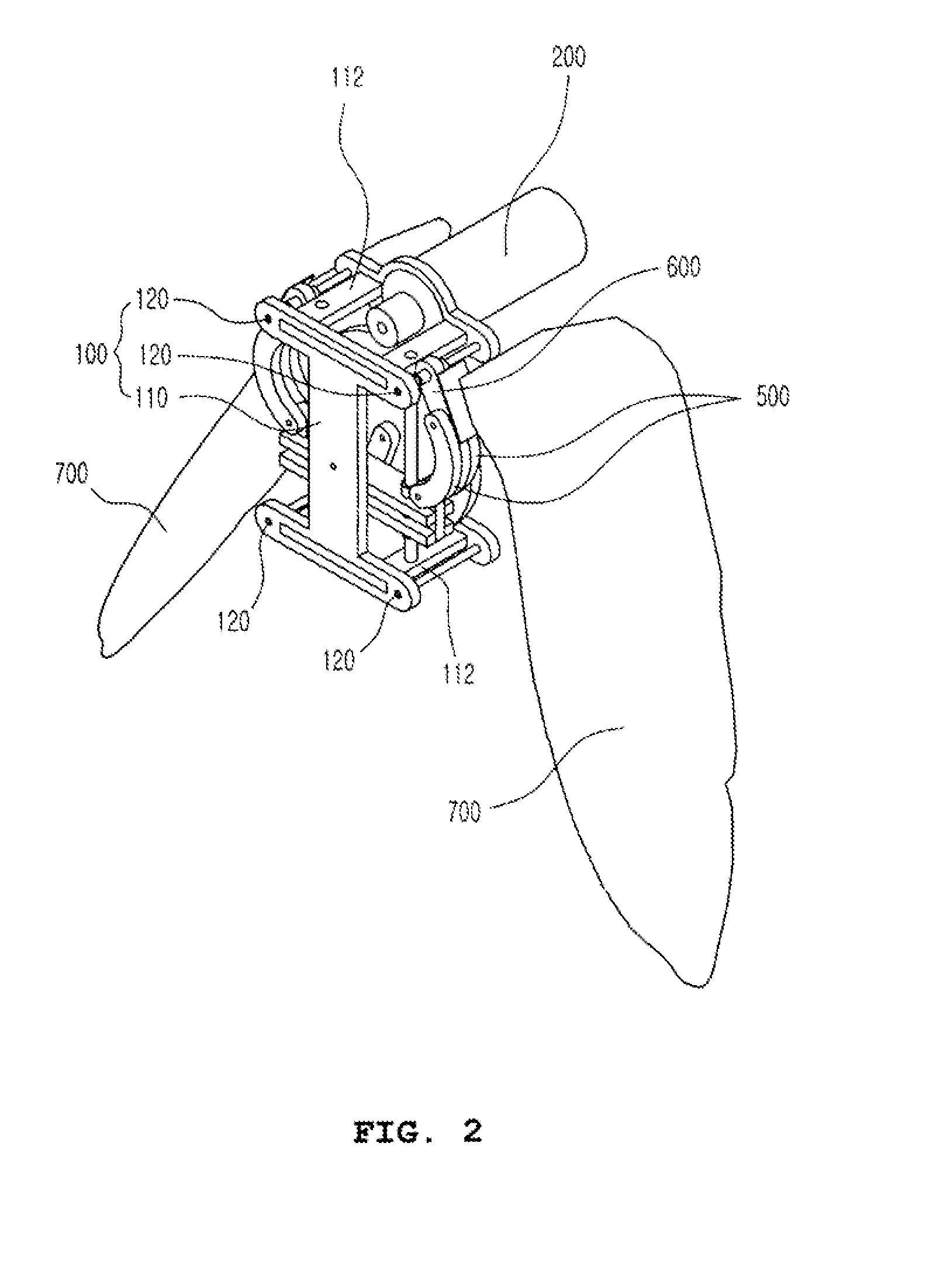
[0022]A flapping apparatus with a large flapping angle according to an embodiment of the present invention is an insect-mimicking flapping apparatus which implements motion similar to the flapping of an insect, such as a beetle, having large flapping motion.

[0023]FIG. 8 is a conception view showing a right side of a connection unit whic...


PUM


Abstract

The present invention provides a flapping apparatus with a large flapping angle. The flapping apparatus includes a frame, a drive motor, a slider, connection links, actuating links and wings. The frame includes I-shaped plates which face each other in parallel, and coupling rods which couple the opposite corners of the upper ends of the I-shaped plates to each other. The drive motor is fastened to the frame such that a rotating shaft thereof is disposed inside the frame. The slider includes lateral bars which are reciprocated upwards and downwards. The connection links are rotatably coupled at first ends thereof to both ends of the lateral bar. The actuating links are rotatably coupled at first ends thereof to second ends of the connection links. The actuating links are rotatably coupled at second ends thereof to the coupling rods. The wings are respectively attached to the upper surfaces of the actuating links.

Description

BACKGROUND OF THE INVENTION[0001]1. Field of the Invention[0002]The present invention relates generally to flapping apparatuses with large flapping angles and, more particularly, to a flapping apparatus which installed in a micro ornithopter and flaps the wings at relatively large angles. Therefore, even though the size of the wings of an ornithopter becomes smaller to reduce the size and weight of the entire body, the dynamic lift sufficient to fly the ornithopter can be generated.[0003]2. Description of the Related Art[0004]Generally, an ornithopter is an aircraft that flies by flapping its wings. Ornithopter research has been steadily conducted since Leonardo da Vinci's design of 1490, and the techniques pertaining thereto have made great and rapid advances. To date, a variety of ornithopters have been introduced. These ornithopters are being widely used, for example, not only as simple toys but also for industrial and military purposes, because remarkable effects can be obtained...

Claims


Application Information

Patent Timeline
IPC IPC(8): B64C33/02
CPCB64C33/02A63H27/001A63H27/008A63H29/10A63H29/22A63H31/08
Inventor PARK, HOON CHEOLNGUYEN, QUOC VIETBYUN, DO YOUNGGOO, NAM SEO
Owner KONKUK UNIV IND COOP CORP
Why Eureka
Try Eureka