Small Magnet and RF Coil for Magnetic Resonance Relaxometry
a small magnet and relaxometry technology, applied in the field of small magnets and rf coils for magnetic resonance relaxometry, can solve the problems of large and/or expensive magnets known to meet these requirements, not suitable for portable devices and/or implantation devices, and/or not suitable as part of disposable probeheads
- Summary
- Abstract
- Description
- Claims
- Application Information
AI Technical Summary
Benefits of technology
Problems solved by technology
Method used
Image

Examples
example 1
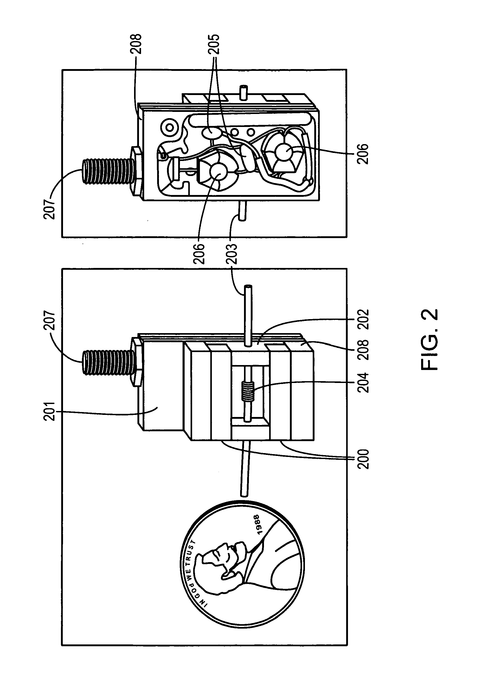
[0090]The probehead of FIG. 2 (also referred herein as “Abe” probehead) was fabricated from a custom machined c-shaped yoke 208 (0.688″×0.5″×0.438″, steel), custom machined electronics enclosure 201 (1″×0.5″×0.5″, aluminum), coil holders 202 (0.19″×0.19″, teflon), magnet positioner (0.438″×0.5″×0.063″, Teflon), sample tube 203 (1 mm O.D., 0.5 mm I.D., 0.6″ long, Teflon), and ten-turn RF coil 204 (32 gage enamel coated copper wire, hand-wound, fastened to the sample tube by lock-tite instant adhesive). The resonant circuit was constructed by a 10-120 pF variable matching capacitor 206, and a combination of a 10-120 pF variable capacitor 206 and two fixed capacitors 205, and a bulkhead SMA connector 207.
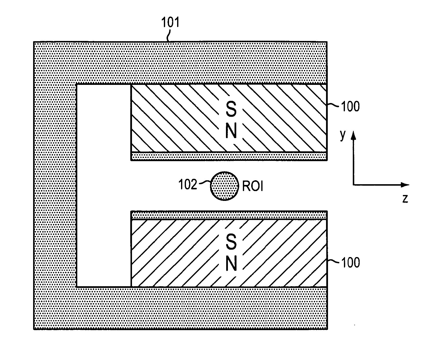
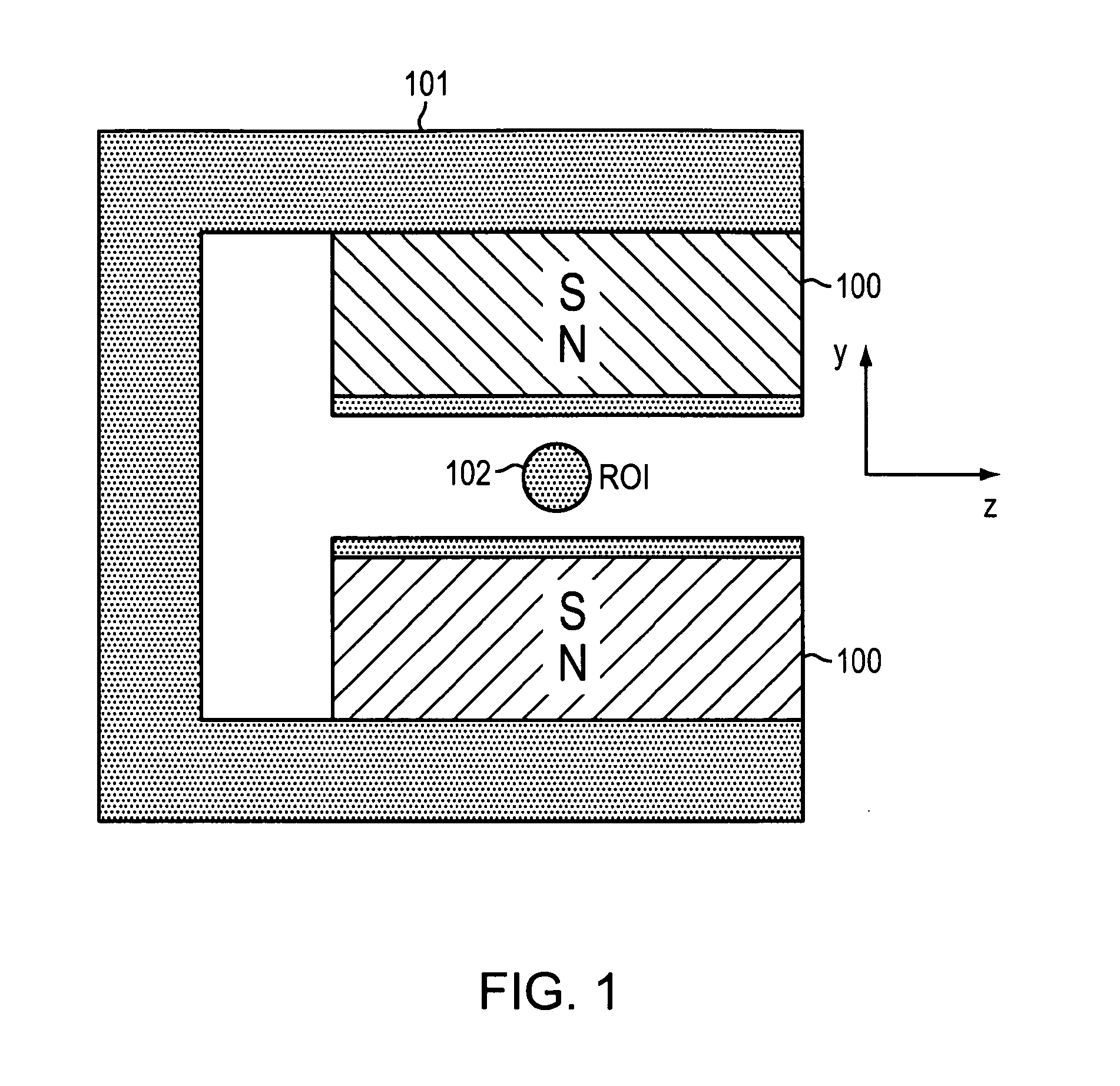
[0091]Two inexpensive, off-the-shelf permanent magnets made of NdFeB 200 were attached to the steel yoke 208 as shown schematically in FIGS. 1 and 5. (FIGS. 1 and 5 show two magnets 100 attached to a c-shaped yoke 101 and a radiofrequency coil 102 positioned between the magnets). The s...
example 2
[0095]Magnet configuration and yoke design can be accomplished initially by a theoretical prediction of what magnet and yoke configuration will lead to in terms of magnetic field strength. This was done by using standard analytical methods. A magnet assembly including two NdFeB permanent magnets (1″×1″×0.5″) 301 was fabricated according to this method (see “T2-yoke” in FIG. 3). The yoke 300 was fabricated from steel stock using standard machining methods. The magnetic field in the x, y, and z directions was determined by fixing a gaussmeter probe relative to the magnet and moving the magnet in incremental steps with a three axis stage while recording the field strength as a function of position. The strength along the x, y, and z axes was measured by fixing two of the three directions to zero while incrementing the other. The same process was conducted for a pre-fabricated Halbach magnet (FIG. 4; the figure shows the Halbach magnet 400 while the magnetic field is being measured with...
PUM
 Abstract
Description
Claims
Application Information
 - R&D Engineer
- R&D Manager
- IP Professional
- Industry Leading Data Capabilities
- Powerful AI technology
- Patent DNA Extraction
Browse by: Latest US Patents, China's latest patents, Technical Efficacy Thesaurus, Application Domain, Technology Topic.
© 2024 PatSnap. All rights reserved.Legal|Privacy policy|Modern Slavery Act Transparency Statement|Sitemap