NMR probe circuit for generating close frequency resonances

a probe circuit and close frequency technology, applied in the field of nmr probe circuits, can solve the problems of circuits, circuits, and inherently unbalanced, and achieve the effect of good balance and isolation

Active Publication Date: 2005-08-23
BRUKER BIOSPIN
View PDF5 Cites 69 Cited by
  • Summary
  • Abstract
  • Description
  • Claims
  • Application Information

AI Technical Summary

Problems solved by technology

One of the problems faced by multiple resonance probes arises when two of the “resonances” are closely spaced in frequency.
However, for elements having resonant frequencies closer together (such as 1H and 19F), it becomes more difficult to get good frequency discrimination between them.
Although this design successfully applies both high resonant frequencies to the sample coil, it is inherently unbalanced, in that the peak of the magnetic field distribution is not in the center of the sample coil for both the high frequency and the low frequency resonances.
In addition, the circuit necessary to support this design, if made small enough to fit within the standard-sized bore of a NMR magnet, would be relatively inefficient.
While this circuit can be effective for lower frequencies, it does not achieve the necessary separation between resonances at higher frequencies (i.e., above 400 Mhz).
However, in this design, all of the channels are on the same side of the sample coil, making the circuit inherently unbalanced.
In addition, the circuit is physically very large, making it difficult to fit in a standard bore.
However, the probe requires a high number of transmission lines very strategically placed around the sample coil.

Method used


Image

  • NMR probe circuit for generating close frequency resonances
  • NMR probe circuit for generating close frequency resonances
  • NMR probe circuit for generating close frequency resonances

Examples


Embodiment Construction

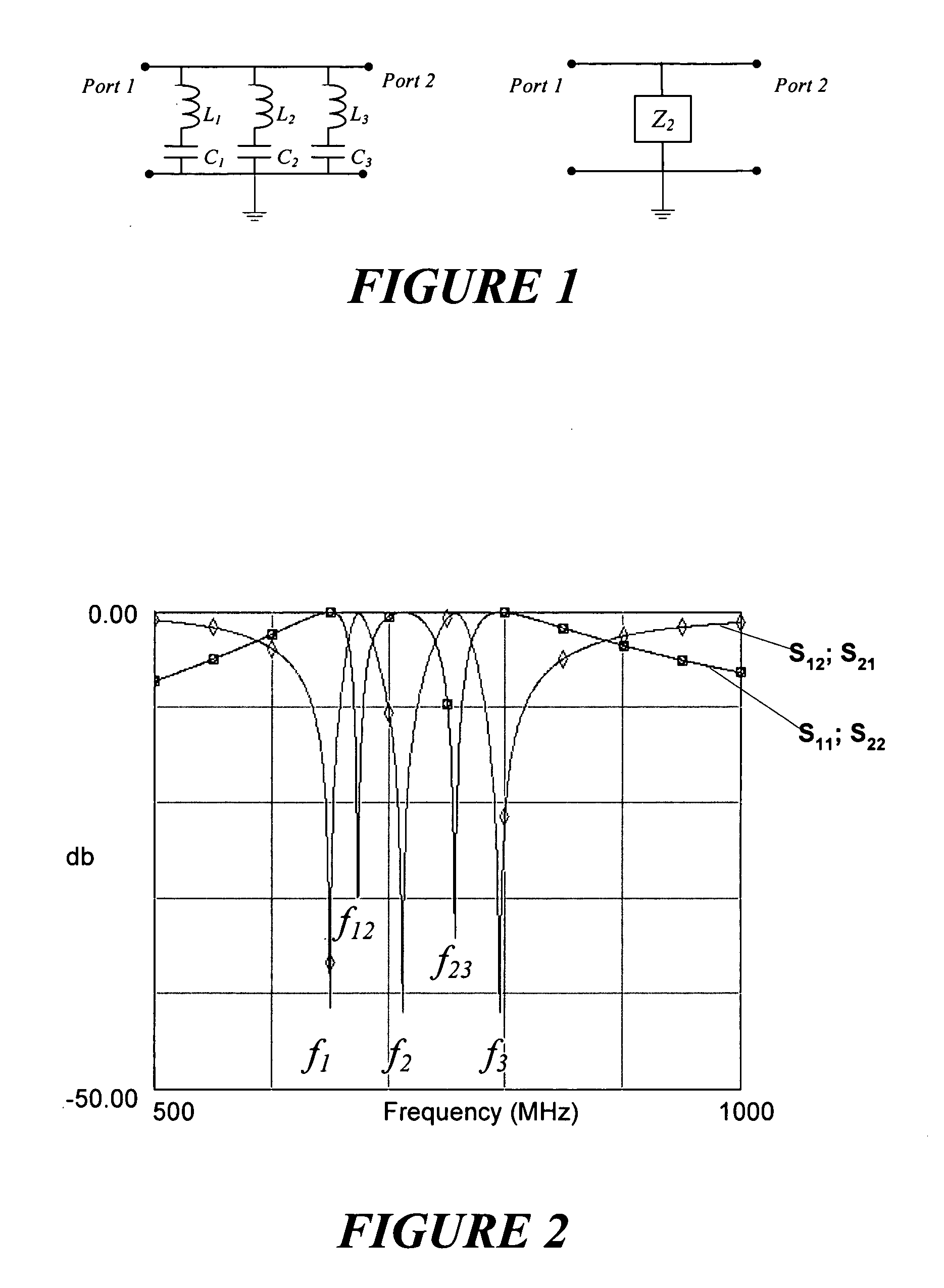
[0017]FIG. 1 shows a schematic depiction of a circuit having three parallel resonators L1C1, L2C2 and L3C3, which together may be represented as a total shunt impedance Z2. Mathematically, Z2 can be represented by the expression: Z2=j⁡(ω2⁢L1⁢C1-1)⁢(ω2⁢L2⁢C2-1)⁢(ω2⁢L3⁢C3-1)ω⁡(a⁢⁢ω4+b⁢⁢ω2+c)

where;

a=C1C2C3(L1L2+L2L3+L3L1)

b=−(L1C1C2+L1C1C3+L2C2C1+L2C2C3+L3C3C1+L3C3C2)

c=C1+C2+C3

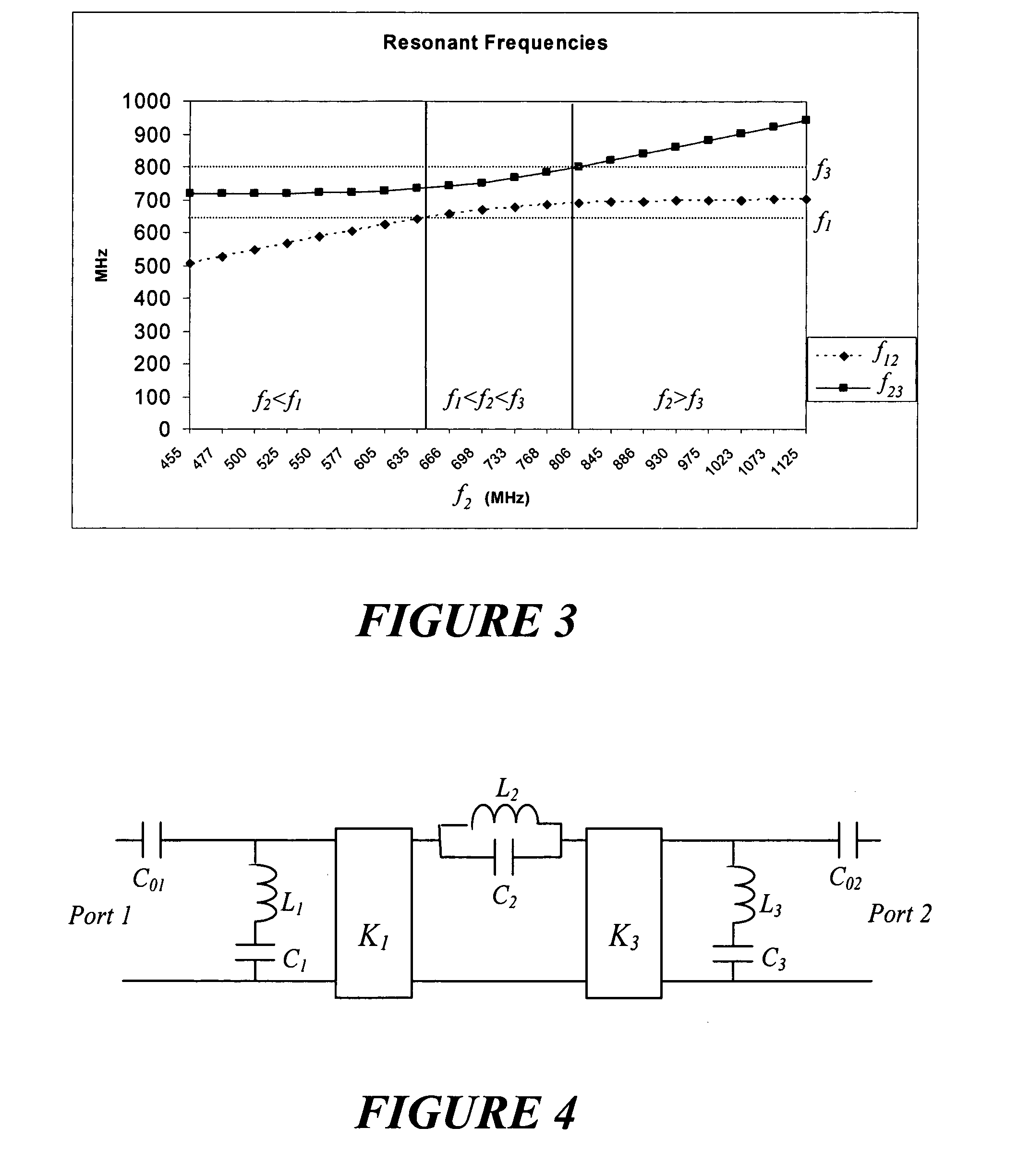
From this, it may be seen that there are three transmission zeroes that occur, respectively, at: f1=12⁢π⁢L1⁢C1,f2=12⁢π⁢L2⁢C2,f3=12⁢π⁢L3⁢C3(5)

Meanwhile, three transmission poles occur, one at DC and the others at: f12,f23=-b±b2-4⁢a⁢⁢c8⁢π2⁢a(6)

Thus, the simulated resonances for this circuit may be plotted as shown in FIG. 2. In this figure, a first plot shows the frequency response as would be detected at Port 1 of the circuit in FIG. 1 when a signal is injected at Port 2 (S12), or as would be detected at Port 2 when a signal is injected at Port 1 (S21). The second plot shows the frequency response that would be de...


PUM


Abstract

A circuit for a nuclear magnetic resonance probe uses three resonators to create resonances intermediate to the resonator resonant frequencies. The circuit is particularly useful for creating magnetic fields for two closely spaced high frequencies, such as those used for the excitation of 1H and 19F. The resonators are arranged in a parallel combination, or the electrical equivalent thereof, with input ports connected to it for inputting the desired high frequency resonances. Admittance inverters may be used to provide isolation between the input ports. Some of the resonators and the admittance inverters may be transmission lines. The transmission lines may have additional ports for additional input signals of lower frequencies located at null points for the frequencies of the signals coupled to the primary input ports. Adjustable dielectric components in the resonator transmission lines may be used for tuning purposes.

Description

FIELD OF THE INVENTION[0001]This invention relates generally to the field of nuclear magnetic resonance (NMR) spectroscopy and, more particularly, to an NMR probe circuit having multiple simultaneous resonances.BACKGROUND OF THE INVENTION[0002]In the field of NMR spectroscopy, a sample is surrounded by an NMR probe that consists of a radio frequency (RF) coil tuned to generate a field at a desired excitation frequency and receive a return NMR signal. More complex probes will generate multiple frequencies so as to excite the nuclei of more than one different element in the sample (e.g., hydrogen nuclei 1H (proton) and fluorine nuclei 19F). These “double resonance” probes (in the case of a probe generating two separate frequencies) and “triple resonance” probes (in the case of a probe generating three separate frequencies) have been used for many years, with varying degrees of success. One of the problems faced by multiple resonance probes arises when two of the “resonances” are close...

Claims


Application Information

Patent Timeline
Patent Type & Authority Patents(United States)
IPC IPC(8): G01R33/32G01R33/36G01R33/34
CPCG01R33/3635G01R33/34092
Inventor LIM, YIT AUNMAAS, WERNER E.
Owner BRUKER BIOSPIN
Why Eureka
Try Eureka