
Projection apparatus and cooling device thereof

a technology of projection apparatus and cooling device, which is applied in the direction of projectors, color television details, instruments, etc., can solve the problems of thermal shutdown, difficult to effectively and excessive heat in the projection apparatus, so as to reduce noise and dissipate the heat generated

Active Publication Date: 2010-12-09
DELTA ELECTRONICS INC
View PDF3 Cites 9 Cited by
  • Summary
  • Abstract
  • Description
  • Claims
  • Application Information

AI Technical Summary

Benefits of technology

[0009]The objective of the present invention is to provide a projection apparatus and a cooling device thereof. The cooling device is adapted to satisfy the heat dissipation requirement of light sources by using the least number of fans, thereby outwardly dissipating the heat generated by the projection apparatus efficiently and reducing the noise.

Problems solved by technology

When used in a meeting presentation or playing movies, a projection apparatus generally operates for an extended period of time, thereby generating excessive heat in the projection apparatus.
However, as the projection apparatus is often equipped with a plurality of light sources, it is sometimes difficult to effectively dissipate the heat generated by these light sources by use of a single fan, thereby causing a thermal shutdown.
Hence, it is very difficult to satisfy the heat dissipation requirements of the different colored LEDs by using a single fan.
Unfortunately, this adds to the cost and occupies a large space, and moreover, noises that are frequently generated during the operation of the fans have an impact on the quality of the presentation.

Method used


Image

  • Projection apparatus and cooling device thereof
  • Projection apparatus and cooling device thereof

Examples


Embodiment Construction

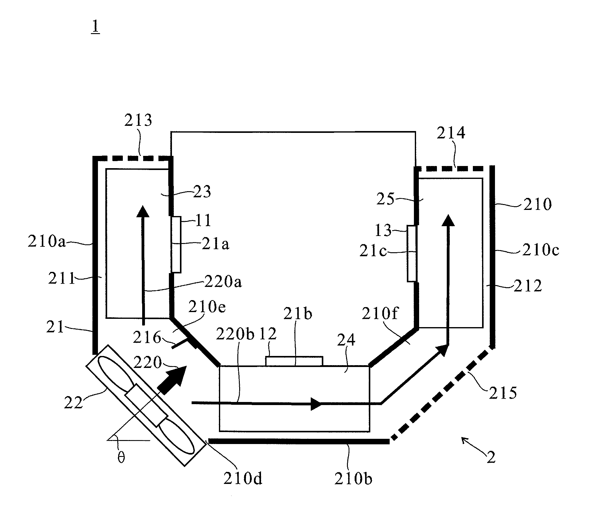
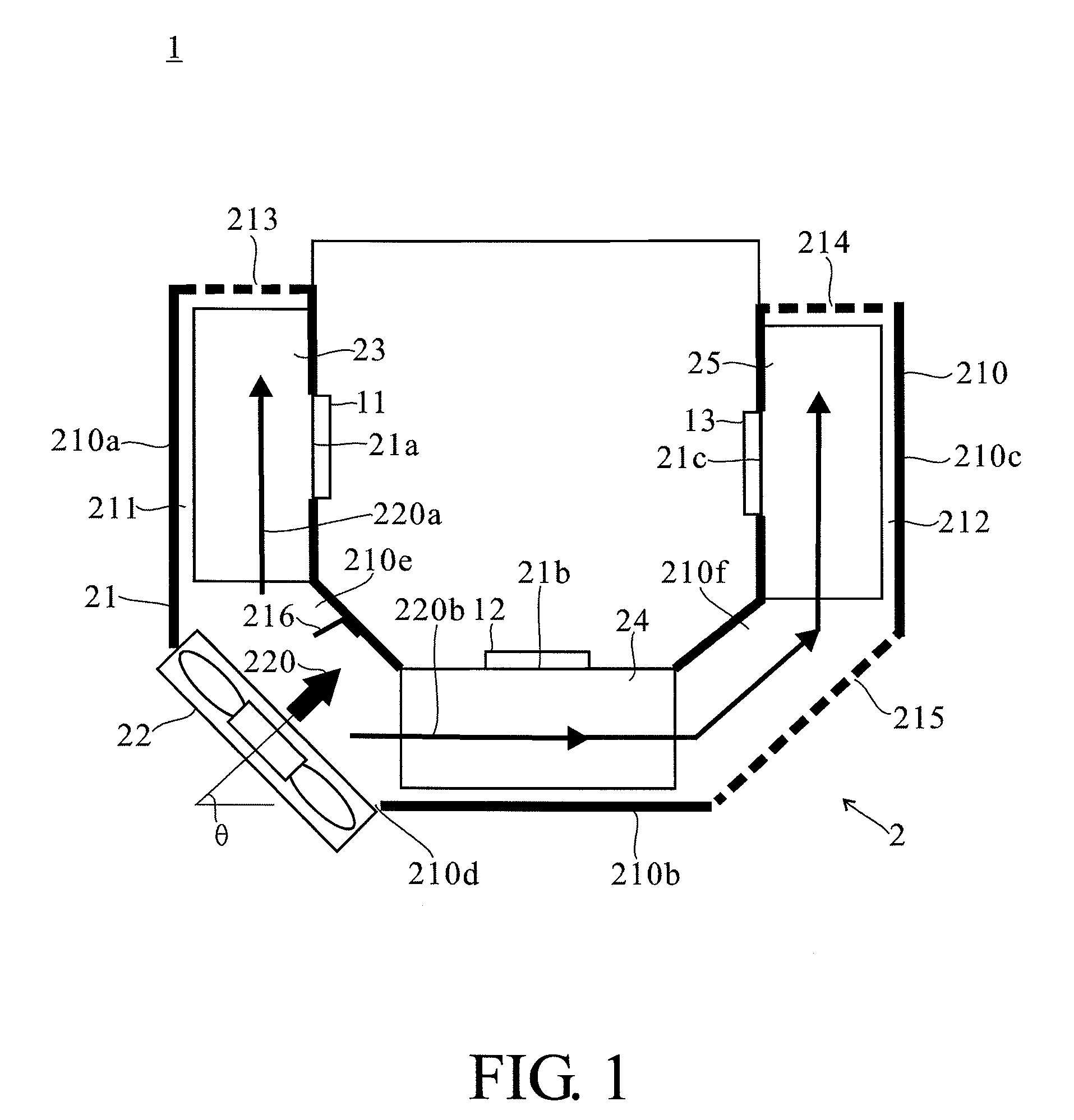
[0013]FIG. 1 illustrates a projection apparatus 1 according to an embodiment of the present invention comprises a first light source 11, a second light source 12, a third light source 13 and a cooling device 2. To illustrate the cooling device 2 of the present invention clearly, other elements of the projection apparatus 1 that are unrelated to the present invention are not depicted in FIG. 1. The cooling device 2 comprises an airflow guiding device 21 and a fan 22. The airflow guiding device 21 is adapted to define a first flow path 211 and a second flow path 212. The end of the first flow path 211 and the end of the second flow path 212 are formed with a plurality of air vents 213, 214 respectively.

[0014]The fan 22 is adapted to generate an air flow 220 which, when entering the first flow path 211 and the second flow path 212 respectively, are divided into a first airflow 220a and a second airflow 220b respectively. The first flow path 211 has a first position 21a, while the secon...


PUM


Abstract

A cooling device applied in a projection apparatus and the projection apparatus are provided. The projection apparatus comprises a first light source, a second light source, a third light source and the cooling device. The cooling device comprises an airflow guiding device and a fan. The airflow guiding device is adapted to define a first flow path and a second flow path. The first flow path has a first position, while the second flow path has a second position and a third position, correspondingly disposed with the first light source, the second light source and the third light source, respectively. The fan is adapted to generate airflow. The airflow is divided into a first airflow and a second airflow entering the first flow path and the second flow path, respectively. Thereby, the cooling device is capable of matching the heat dissipation requirements of the light sources and reducing the noise generated by the cooling device by using only one fan.

Description

[0001]This application claims priority to Taiwan Patent Application No. 098118532 filed on Jun. 4, 2009, the disclosures of which are incorporated herein by reference in their entirety.CROSS-REFERENCES TO RELATED APPLICATIONS[0002]Not applicable.BACKGROUND OF THE INVENTION[0003]1. Field of the Invention[0004]The present invention relates to a projection apparatus, and particularly, to a cooling device applied in a projection apparatus.[0005]2. Descriptions of the Related Art[0006]Projection apparatuses have found a wide application in various business meetings and home theaters. When used in a meeting presentation or playing movies, a projection apparatus generally operates for an extended period of time, thereby generating excessive heat in the projection apparatus. To prevent shutdown and premature failure of the projection apparatus due to excessive heat, a fan is often provided in the prior art to dissipate heat generated during the operation of the projection apparatus.[0007]Ge...

Claims


Application Information

Patent Timeline
Patent Type & Authority Applications(United States)
IPC IPC(8): G03B21/16
CPCH04N9/3144G03B21/16
Inventor WANG, CHUN-CHIEHCHANG, REN-CHUNLIN, WEI-ZHI
Owner DELTA ELECTRONICS INC
Learn More