Start-up Circuit to Discharge EMI Filter for Power Saving of Power Supplies

a technology of emi filter and power supply, applied in the field of power supply, can solve the problems of poor power saving at light-load and no-load, bleeding resistor rsub>d /sub>consumption of standby power, and power saving in switching mode power supply has drawn much attention

Active Publication Date: 2010-12-09
SEMICON COMPONENTS IND LLC
View PDF4 Cites 61 Cited by
  • Summary
  • Abstract
  • Description
  • Claims
  • Application Information

AI Technical Summary

Problems solved by technology

In recent years, the problem of power saving in switching mode power supplies has drawn much attention.
Besides, for higher power source, the bleeding resistor RD consumes m

Method used


Image

  • Start-up Circuit to Discharge EMI Filter for Power Saving of Power Supplies
  • Start-up Circuit to Discharge EMI Filter for Power Saving of Power Supplies
  • Start-up Circuit to Discharge EMI Filter for Power Saving of Power Supplies

Examples


Embodiment Construction

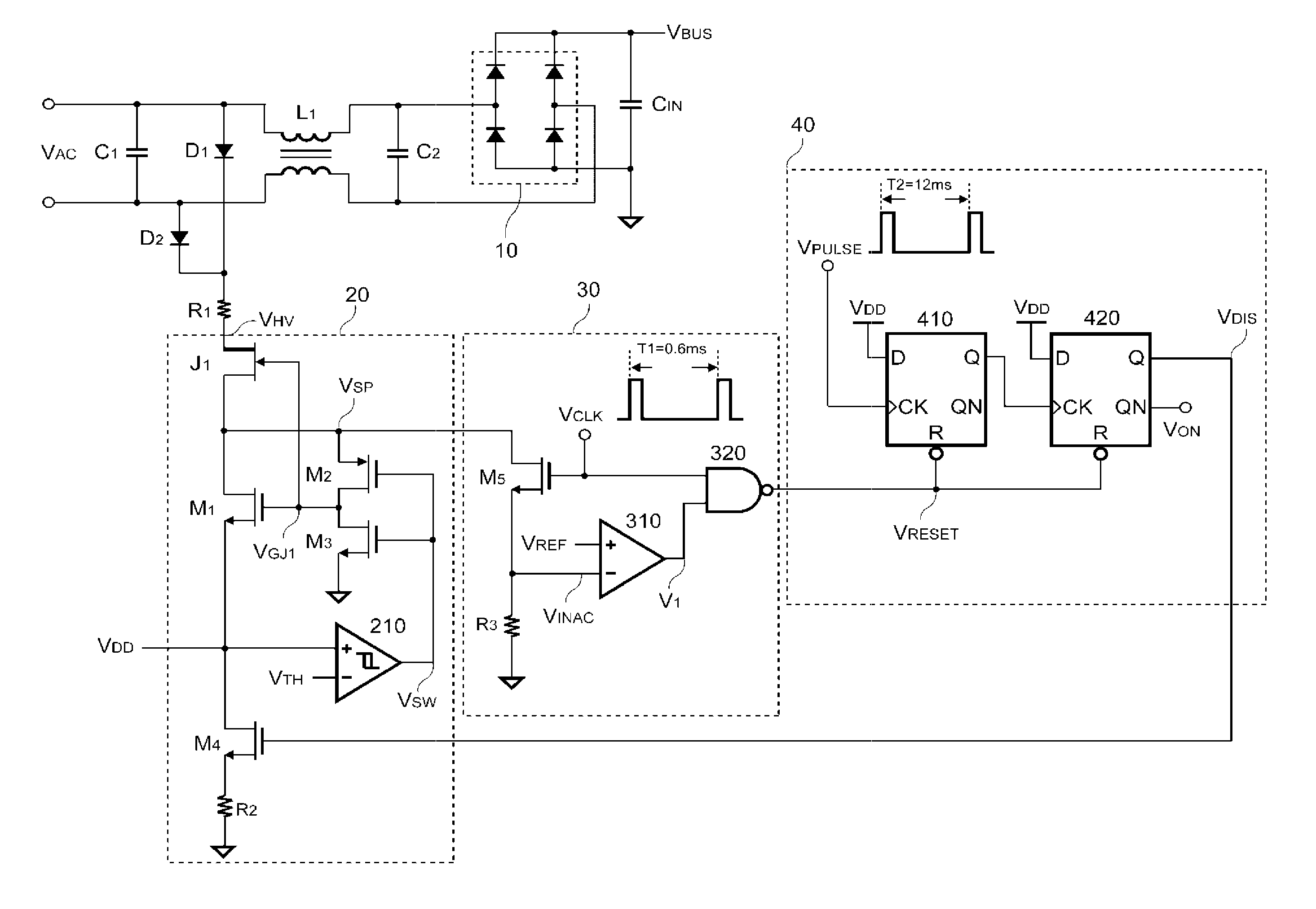
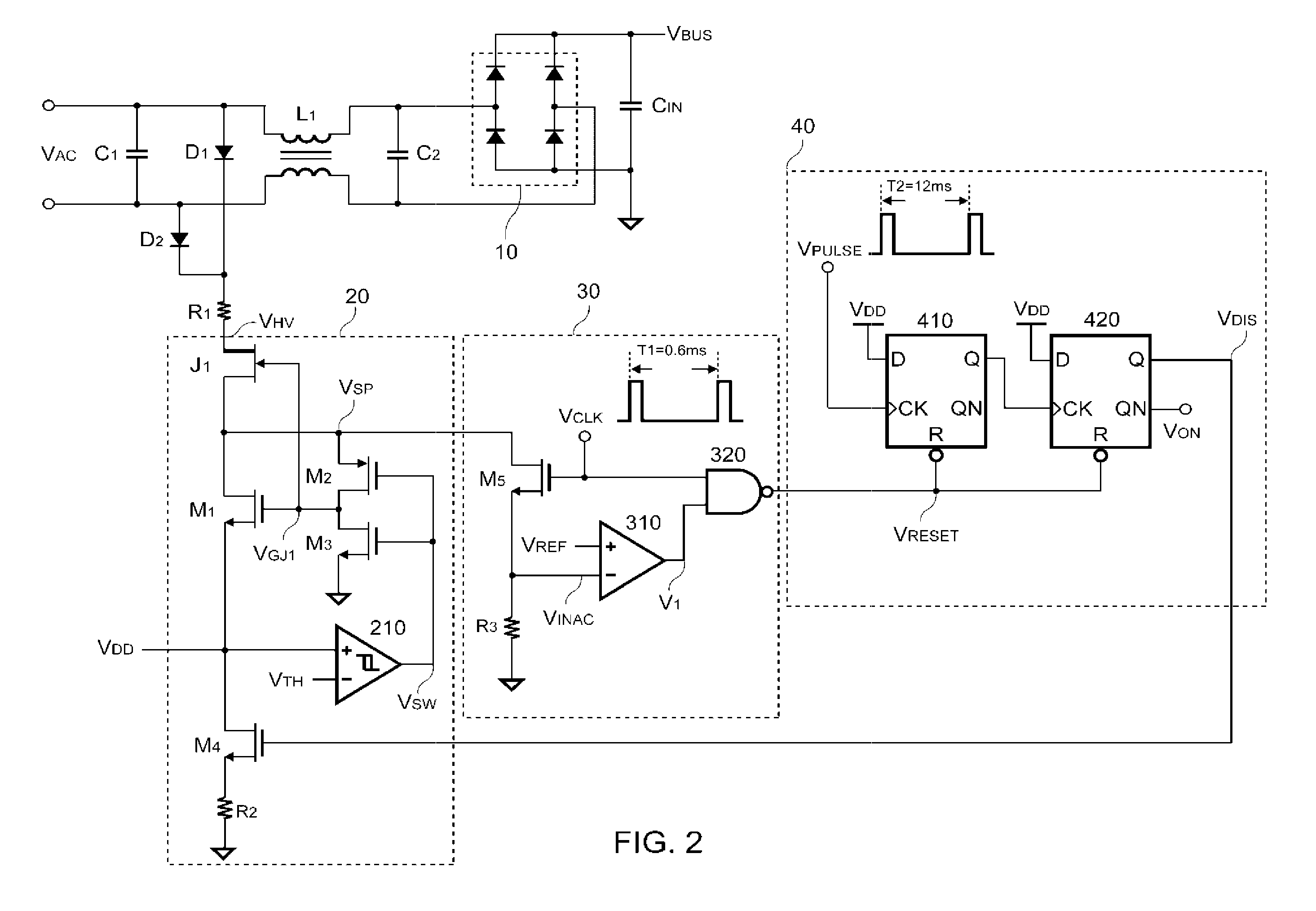
[0011]FIG. 2 is a preferred embodiment of a start-up circuit according to the present invention. The start-up circuit is utilized to discharge the EMI filter for power saving of power supplies. The EMI filter includes the choke L1, X-capacitors C1 and C2, the bulk capacitor CIN, and the bridge rectifier 10 for filtering EMI and providing the DC voltage VBUS. The start-up circuit includes a rectifier, a series resistor R1, a detection circuit 20, a sample circuit 30 and a delay circuit 40. The rectifier can be a full-wave rectifier having a first diode D1 and a second diode D2 according to one embodiment of the present invention, Anodes of the first diode D1 and the second diode D2 are connected to the power source VAC respectively. Cathodes of the first diode D1 and the second diode D2 are together connected to one terminal of the series resistor R1. The other terminal of the series resistor R1 generates a high-voltage signal VHV through the full-wave rectification of the first diod...


PUM


Abstract

A start-up circuit to discharge EMI filter is developed for power saving. It includes a detection circuit detecting a power source for generating a sample signal. A sample circuit is coupled to the detection circuit for generating a reset signal in response to the sample signal. The reset signal is utilized for discharging a stored voltage of the EMI filter.

Description

BACKGROUND OF THE INVENTION[0001]1. Field of Invention[0002]The present invention relates to a power supply, and more particularly, the present invention relates to a start-up circuit.[0003]2. Description of Related Art[0004]Switching mode power supplies have been widely used to provide regulated power for computers, home appliances, communication equipments, etc. In recent years, the problem of power saving in switching mode power supplies has drawn much attention. Based on the restriction of environmental pollution, the computer and other equipment manufactures have been striving to meet the power management and energy conservation requirements.[0005]FIG. 1 shows a traditional approach for filtering electromagnetic interference (EMI) and providing a DC voltage. An EMI filter located between a power source VAC and a bridge rectifier 10 includes a choke L1, X-capacitors C1 and C2. The X-capacitor C1 is placed across the power source VAC. The choke L1 is coupled between the power sou...

Claims


Application Information

Patent Timeline
IPC IPC(8): H02M1/00
CPCH02M1/126H02M1/14H02M2001/322H02M1/36H02M1/322
Inventor HUANG, WEI-HSUANTSAI, MENG-JENLIN, CHIEN-YUANTSOU, MING-CHANGLI, CHUAN-CHANGWANG, GWO-HWA
Owner SEMICON COMPONENTS IND LLC
Why Eureka
Try Eureka