Memory management

a memory management and memory technology, applied in the field of methods, can solve the problems of inefficient memory usage, high usage of memory 104/b>, and it is relatively difficult to identify a suitable memory region in response to a dynamic memory allocation

Active Publication Date: 2010-12-09
NXP USA INC
View PDF8 Cites 23 Cited by
  • Summary
  • Abstract
  • Description
  • Claims
  • Application Information

AI Technical Summary

Problems solved by technology

Whilst the programmer could elect to statically allocate enough memory (for example, based on a worst-case-estimate predicting the largest amount of memory that could possibly be required), this would be inefficient memory usage as it leaves less of the memory 104 available for use by other processes.
However, once the computer system 100 has been running for some time, and is executing a large number of processes, the usage of the memory 104 may be quite high and so it will be relatively harder to identify a suitable memory region in response to a dynamic memory allocation request.
This is compounded by the fact that the memory 104 will become fragmented over time, i.e. portions of allocated memory will be interleaved with portions of free memory, which may therefore make it harder to find a contiguous memory region of a requested size, even though the combined amount of free memory (when considered as non-fragmented memory) may still be more than sufficient for the requested allocation size.
Additionally, when an application has been developed for one computer platform 100, but is to be ported across to a different platform, the methods and styles of memory allocation used for the application may not be suitable for this different platform (due to factors such as different sizes of memory available on different platforms and different processing power between different platforms).
Thus, integrating the various different modules and re-working an application for a different computing platform can occupy a large amount of a development project lifetime, in terms of analysis of memory usage and allocation, development and testing of the various modules and their integration and optimisation.
These checks can be a very involved task.

Method used


Image

  • Memory management
  • Memory management
  • Memory management

Examples


Embodiment Construction

[0056]In the description that follows and in the figures, certain embodiments of the invention are described. However, it will be appreciated that the invention is not limited to the embodiments that are described and that some embodiments may not include all of the features that are described below. It will be evident, however, that various modifications and changes may be made herein without departing from the broader scope of the invention as set forth in the appended claims.

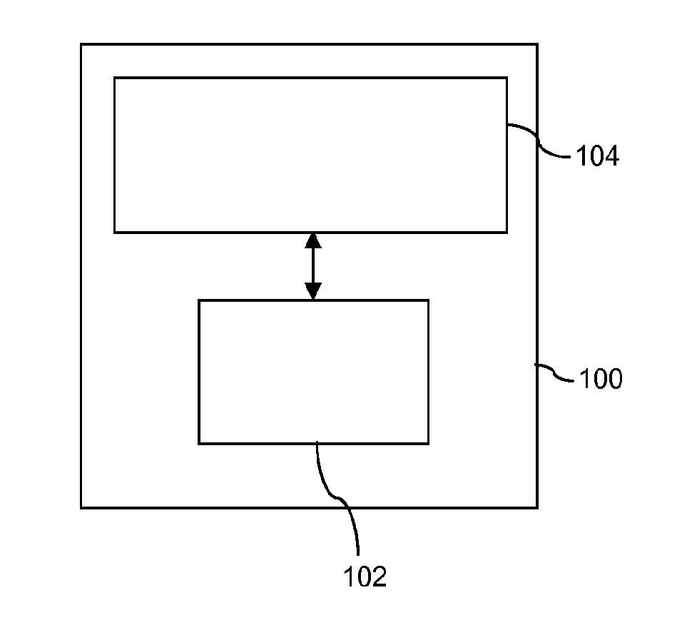
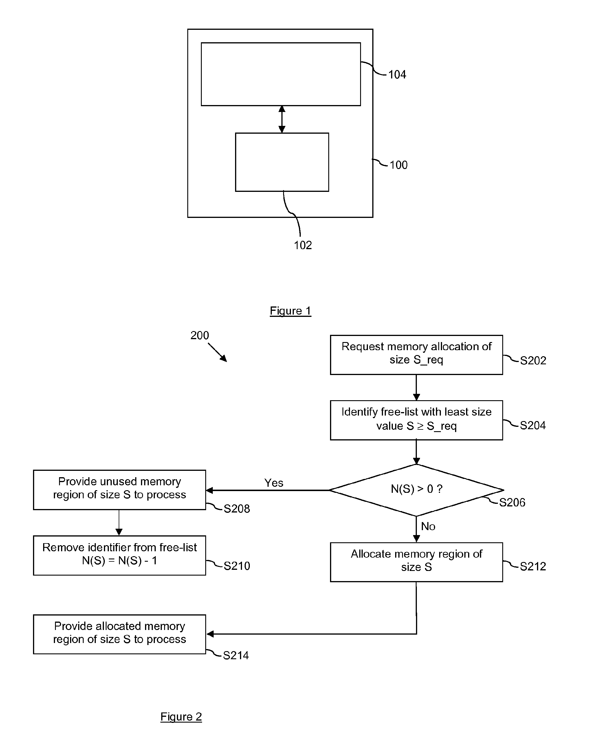
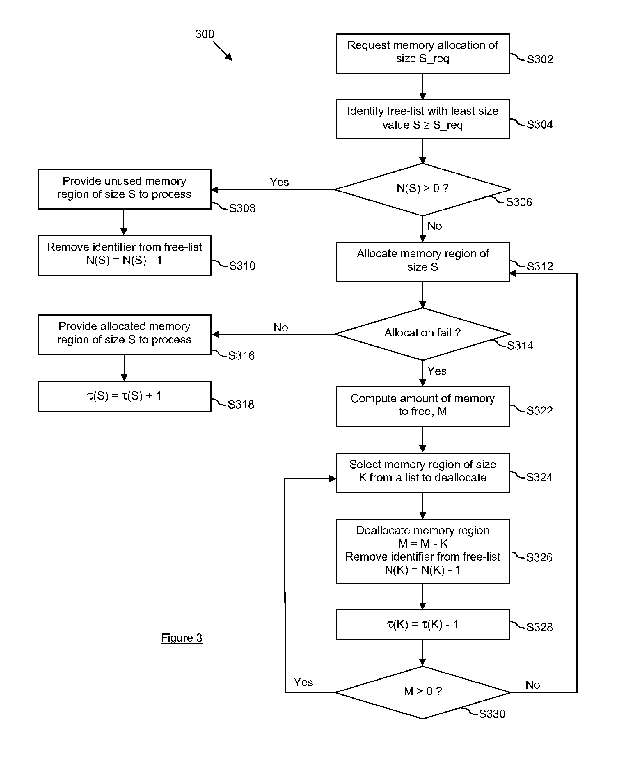
[0057]Embodiments of the invention make use of free-lists, which have been described above. However, in contrast to the use of free-lists as described above, in embodiments of the invention, the processor 102 of the computer system 100 may adjust the thresholds associated with the free-lists being used, i.e. the thresholds need not be predetermined. This adjustment is based primarily on the current usage of the memory 104 by the one or more processes that are being executed.

[0058]This will be described in mor...


PUM


Abstract

A method of managing a memory of an apparatus the apparatus executing one or more processes using the memory. The method comprises maintaining a plurality of lists of identifiers, wherein each list has an associated size value and an associated threshold corresponding to a maximum number of identifiers in that list, wherein each identifier identifies a corresponding region of the memory that had been allocated for a process but that is currently not required by any of the one or more processes, and wherein the size of a region of the memory identified by an identifier of a list equals the size value associated with that list. When a process requests allocation of a region of the memory: one of the lists are identified that has an associated size value suitable for the allocation request; and if that list is not empty, to that process a region is identified of the memory identified by one of the identifiers stored in that list and that identifier is removed from that list, and, otherwise, a region of the memory is allocated with a size of the identified associated size value and the allocated region is identified of the memory to that process. The method comprises adjusting one or more of the thresholds in dependence upon the current usage of the memory by the one or more processes.

Description

FIELD OF THE INVENTION[0001]The present invention relates to a method of managing a memory of an apparatus, and an apparatus and a computer program arranged to carry out such a methodBACKGROUND OF THE INVENTION[0002]Various methods of memory allocation and deallocation for computer systems are known. FIG. 1 of the accompanying drawings schematically illustrates a computer system 100. The computer system 100 comprises a processor 102 and a memory, such as a random access memory (RAM) 104. The computer system 100 may be, for example, a personal computer, a portable device (such as a mobile telephone or a personal digital assistant), an embedded system, a network of several computers, or any computing platform, etc. It will be appreciated that the computer system 100 may comprise more than one processor 102, with these processors either operating independently of each other or working together. It will also be appreciated that the computer system 100 may comprise one or more RAMs 104. ...

Claims


Application Information

Patent Timeline
Patent Type & Authority Applications(United States)
IPC IPC(8): G06F12/02G06F12/00
CPCG06F12/023G06F12/0615G06F2212/251G06F2212/702
Inventor ROBIN, JEAN-LUCMENDES-CARVALHO, JOSE
Owner NXP USA INC
Why Eureka
Try Eureka