Test procedure to determine concentration and relative distribution of sized particles in a drilling fluid

Inactive Publication Date: 2010-12-16
MI
View PDF21 Cites 20 Cited by
  • Summary
  • Abstract
  • Description
  • Claims
  • Application Information

AI Technical Summary

Problems solved by technology

While it is highly advantageous to maintain the wellbore pressures above the pore pressure, on the other hand, if the pressure exerted by the wellbore fluids exceeds the fracture resistance of the formation, a formation fracture and thus induced mud losses may occur.
Therefore, a major constraint on well design and selection of drilling fluids is the balance between varying pore pressures and formation fracture pressures or

Method used


Image

  • Test procedure to determine concentration and relative distribution of sized particles in a drilling fluid
  • Test procedure to determine concentration and relative distribution of sized particles in a drilling fluid
  • Test procedure to determine concentration and relative distribution of sized particles in a drilling fluid

Examples


example 1

Portable Wet-Sieving Device Test

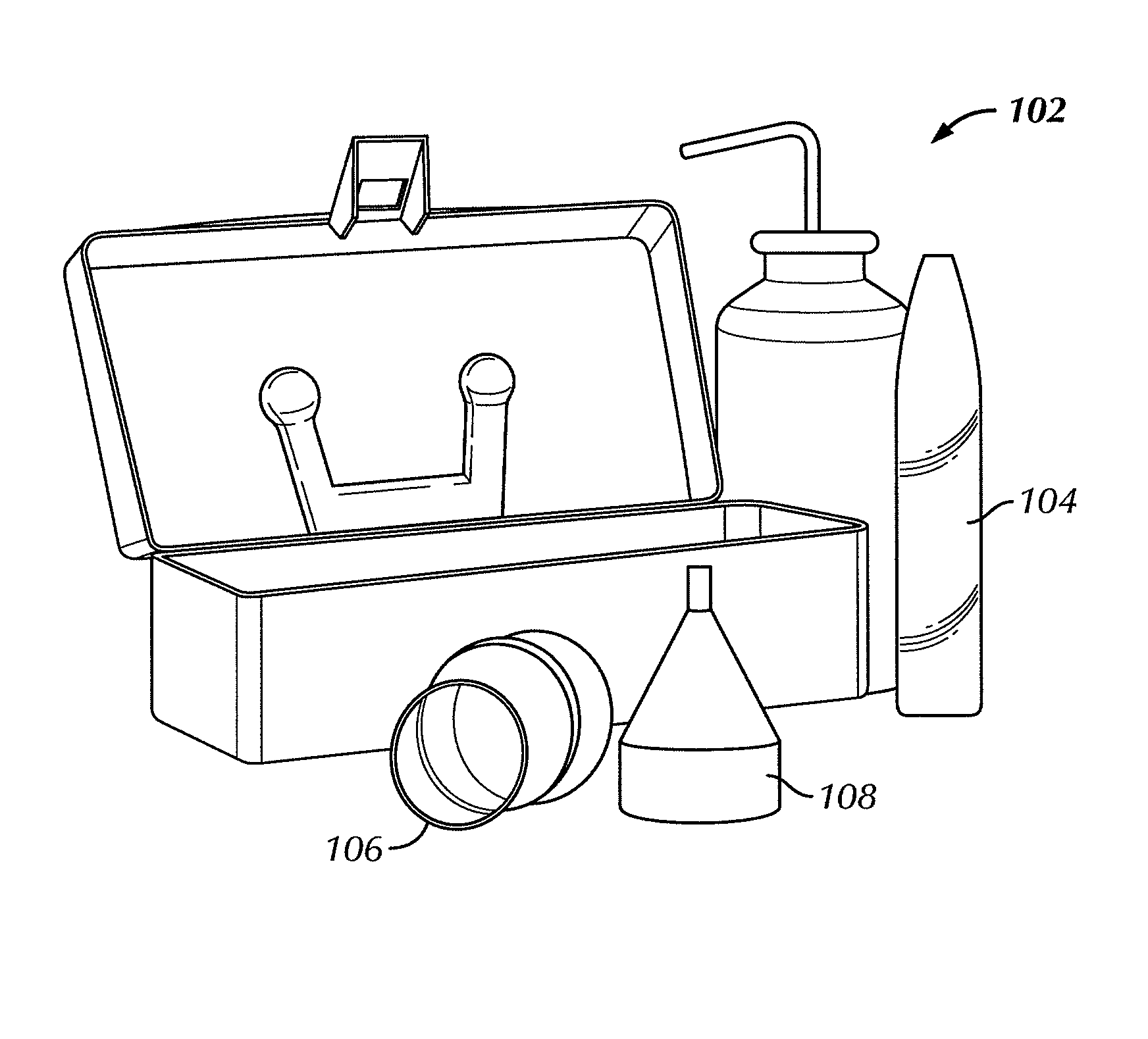
[0068]An example of a portable wet-sieving device in accordance with embodiments disclosed herein is now described. As shown in FIGS. 8A-8D, the portable wet-sieving device 220 includes a section of PVC-DWV 222, schedule 40, with a 3 inch inner diameter, 3 7 / 16 inch outer diameter, and approximately 1.5 feet long, three flexible rubber couplings 230 with 3⅜ inch inner diameters, two PVC-DWV schedule 40 couplings 224 with 3 inch inner diameters, 3 7 / 16 inch outer diameter, and approximately 2 inches long, eight 3-inch hose clamps 226, and three sieves 228 with 3 inch inner diameters, 3¼ inch outer diameter.

[0069]To assemble the portable wet-sieving device 220, place a hose-clamp 226 on the outside of one of the couplings 230, and insert a sieve 228 into one of the flexible rubber couplings, both about 1.5″ from the top of the coupling. Tighten the clamp 226 until it is snug, allowing for a good seal around the sieve 228. Repeat these steps with the oth...

example 2

Portable Wet-Sieving Device

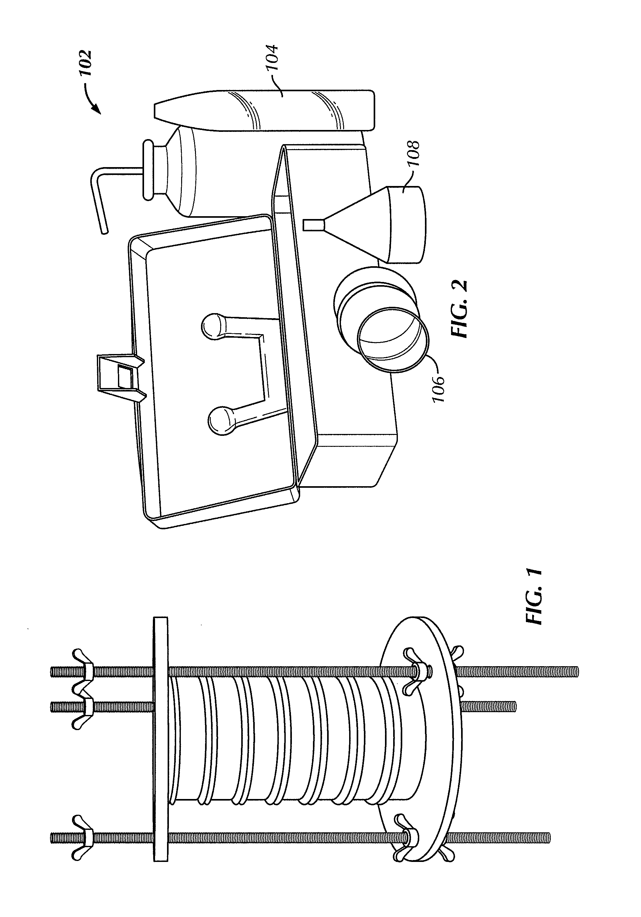
[0082]Another example of a portable wet-sieving device in accordance with embodiments disclosed herein is now described. As shown in FIGS. 9A and 9B, the wet-sieving device includes two flat steel plates, three ¼ inch threaded steel rods that are 1 foot long, nine wing nuts that fit the ¼ inch threaded rods, 3-inch sieves, and o-rings that tightly fit the sieves. The two flat steel plates are ¼ inch thick, have a 6-inch outer diameter, 2.5 inches inner diameter cut out, and three ¼ inch holes are drilled ½ inch from the outer edge of the plates, wherein the holes are spaces at 120 degrees from each other.

[0083]To assemble the wet-sieve device of FIGS. 9A and 9B, the threaded rods are inserted two inches into one plate through the ¼ inch holes. Wing nuts, two for each rod, are treaded onto the rods from both sides of the plate and secured tightly. The apparatus at this point needs to be stood horizontally on the ends of three rods that are closest to the pl...

example 3

Portable Wet-Sieving Device

[0084]Another example of a portable wet-sieving device in accordance with embodiments disclosed herein is now described. As shown in FIGS. 10A and 10B, the wet-sieving device includes two flat steel plates, one C-clamp 3.5 inches by one foot ¼ inch thick, 3-inch sieves, and o-rings that tightly fit the sieves. In this example, the two flat steel plates have 3.5-inch outer diameters, 2.75 inches inner diameter cut out, except for a strip 0.5 inches wide in the middle of the plate.

[0085]To assemble the wet-sieve device of FIGS. 10A and 10B, weld the center of the clamps face, while keeping the plates horizontal, running parallel to each other. Open the clamp and insert a stack of sieves. Each sieve would be fitted with an O-ring to create a seal between two interlocking sieves. Stack the sieves one on the other with the smallest micron sized sieve to the largest micron size sieve. The stack of sieves would then be places on the center of the plates. Tighten ...


PUM


Abstract

A method of determining a particle size distribution in a wellbore fluid including collecting a volume of mud from a vibratory separator, sampling a volume of the collected mud, and testing the volume of collected mud with a test kit to determine the concentration of a sized additive in the mud is disclosed. A system for determining particle size distribution of a fluid, the system including a vibratory separator, a meter configured to receive a separated material from the vibratory separator, a counter configured to count the number of loads collected by the meter, a test kit including a sieve and a measuring tube, and a centrifuged configured to receive the measuring tube is also disclosed.

Description

BACKGROUND[0001]1. Field[0002]Embodiments disclosed herein generally relate to test procedures and apparatus for determining the concentration, quantity, and relative distribution of sized particles in drilling fluids. More specifically, embodiments disclosed herein relate to test procedures and apparatus for determining an amount of an unknown quantity of product (e.g., loss prevention material) being recovered and added to an active mud system.[0003]2. Background Art[0004]During the drilling of a wellbore, various fluids are typically used in the well for a variety of functions. The fluids may be circulated through a drill pipe and drill bit into the wellbore, and then may subsequently flow upward through wellbore to the surface. Common uses for well fluids include: lubrication and cooling of drill bit cutting surfaces while drilling generally or drilling-in (i.e., drilling in a targeted petroliferous formation), transportation of “cuttings” (pieces of formation dislodged by the c...

Claims


Application Information

Patent Timeline
IPC IPC(8): E21B43/38G01N15/02
CPCE21B21/066G01N2015/0019G01N15/0272
Inventor DOMAN, AARON A.GARBER, JAKE M.HERRERA, PHILIP E.BUTLER, FRANKPIERCE, TOBYBROWNING, TIMSMITH, JOHN RIDDELLGROWCOCK, FREDERICK B.
Owner MI
Why Eureka
Try Eureka