Thermokeratoplasty system with a power supply that can determine a wet or dry cornea

a power supply and cornea technology, applied in the field of thermokeratoplasty probes, can solve the problems of glaring effect in the visual field, risk of puncturing the descemets membrane and the endothelium layer, and permanent damage to the ey

Inactive Publication Date: 2006-01-17
REFRACTEC
View PDF51 Cites 60 Cited by
  • Summary
  • Abstract
  • Description
  • Claims
  • Application Information

AI Technical Summary

Problems solved by technology

Penetrating the cornea to such a depth increases the risk of puncturing the Descemets membrane and the endothelium layer, and creating permanent damage to the eye.
Additionally, light entering the cornea at the incision sight is refracted by the incision scar and produces a glaring effect in the visual field.
The glare effect of the scar produces impaired night vision for the patient.
The techniques of radial keratotomy are only effective in correcting myopia.
Radial keratotomy cannot be used to correct an eye condition such as hyperopia.
Additionally, keratotomy has limited use in reducing or correcting an astigmatism.
A flat cornea creates a lens system which does not correctly focus the viewed image onto the retina of the eye.
Although effective in reshaping the eye, the laser based systems of the Baron, Sand and PCT references are relatively expensive to produce, have a non-uniform thermal conduction profile, are not self limiting, are susceptible to providing too much heat to the eye, may induce astigmatism and produce excessive adjacent tissue damage, and require long term stabilization of the eye.
Expensive ...

Method used


Image

  • Thermokeratoplasty system with a power supply that can determine a wet or dry cornea
  • Thermokeratoplasty system with a power supply that can determine a wet or dry cornea
  • Thermokeratoplasty system with a power supply that can determine a wet or dry cornea

Examples


Embodiment Construction

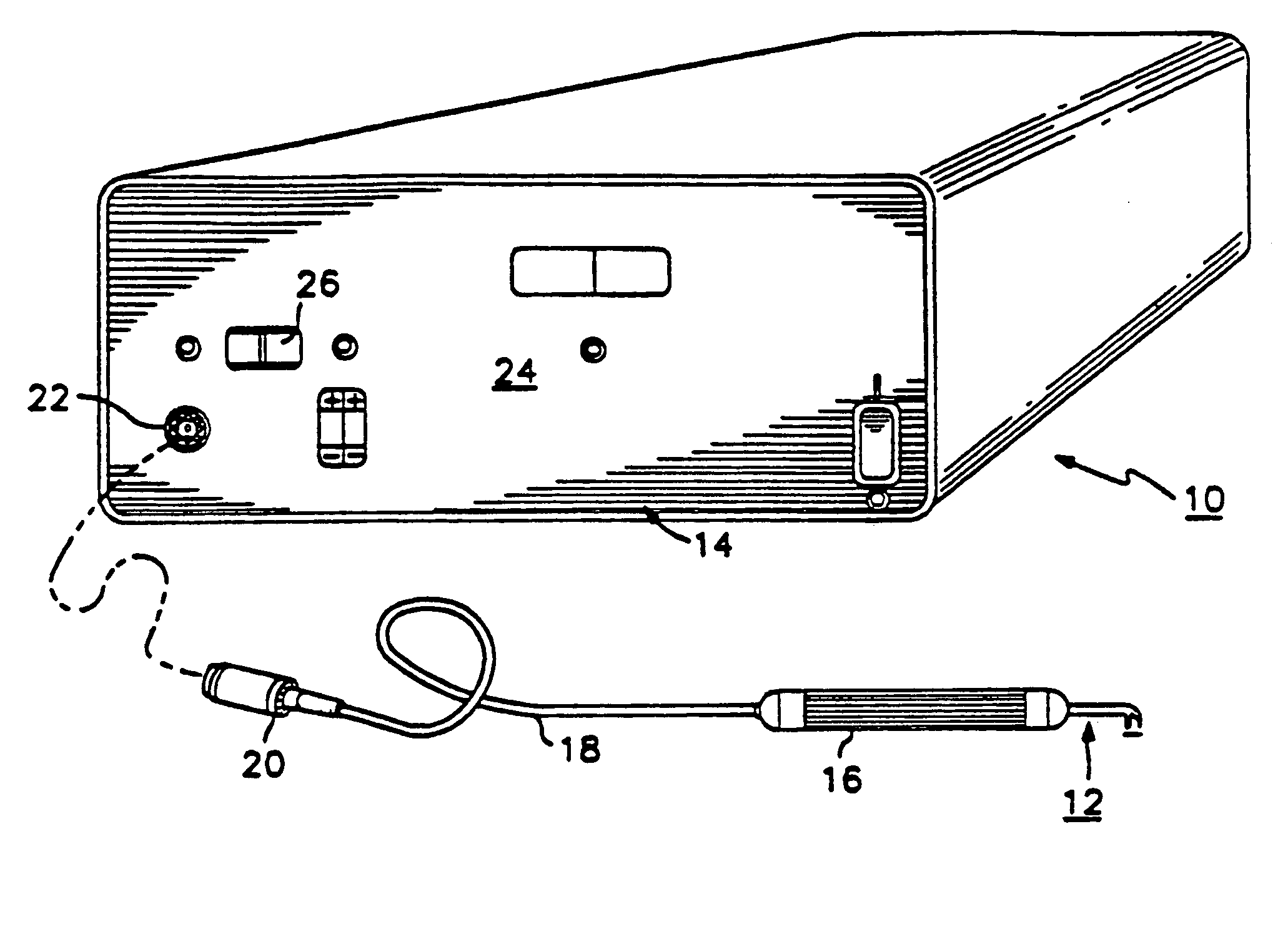
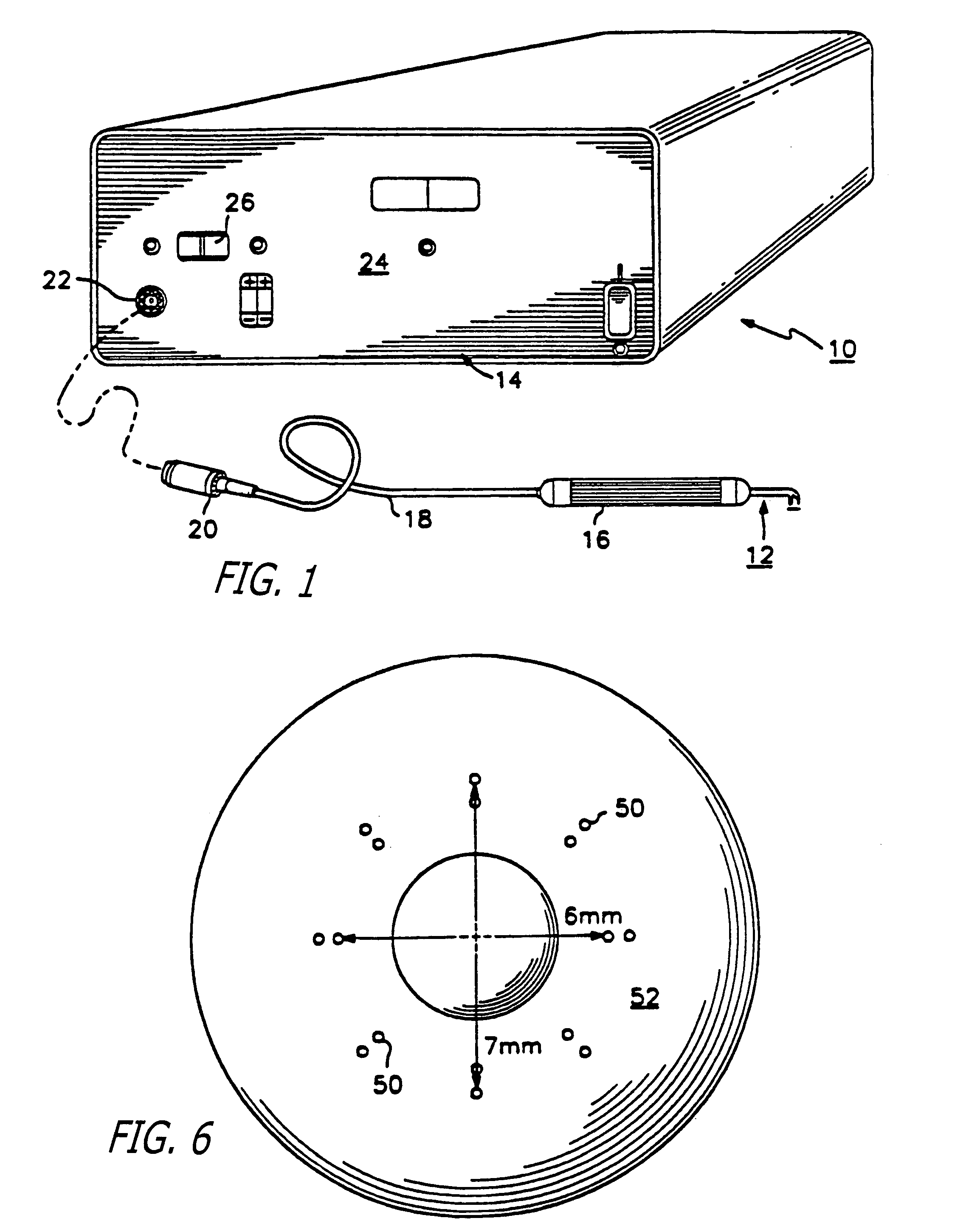
[0056]Referring to the drawings more particularly by reference numbers, FIG. 1 shows a thermokeratoplastic electrode system 10 of the present invention. The system 10 includes an electrode probe 12 coupled to a power supply unit 14. The power supply unit 14 contains a power supply which can deliver power to the probe 12. The probe 12 has a hand piece 16 and wires 18 that couple the probe electrodes to a connector 20 that plugs into a mating receptacle 22 located on the front panel 24 of the power unit. The hand piece 16 may be constructed from a non-conductive material and is approximately 0.5 inches in diameter and 5 inches long.

[0057]The power supply 14 provides a predetermined amount of energy, through a controlled application of power for a predetermined time duration. The power supply 14 may have manual controls that allow the user to select treatment parameters such as the power and time duration. The power supply 14 can also be constructed to provide an automated operation. T...


PUM


Abstract

A power supply for a thermokeratoplasty system. The power supply can be connected to an electrode and a return element that are both coupled to a cornea. The power supply can perform a test routine to determine whether the cornea is too “wet” or too “dry”.

Description

REFERENCE TO RELATED APPLICATIONS[0001]This application is a continuation of application Ser. No. 09 / 539,270, filed on Mar. 30, 2000 now U.S. Pat. No. 6,673,069, and a continuation-in-part of application Ser. No. 09 / 759,684, filed on Jan. 10, 2001, pending, which is a continuation of application Ser. No. 09 / 239,060, filed on Jan. 26, 1999, abandoned, which is a continuation of application Ser. No. 08 / 957,911, filed on Oct. 27, 1997, U.S. Pat. No. 6,213,997, which is a continuation-in-part application Ser. No. 08 / 287,657, filed on Aug. 9, 1994, U.S. Pat. No. 5,749,871, which is a continuation-in-part of application Ser. No. 08 / 171,225, filed on Dec. 20, 1993, abandoned, which is a continuation-in-part of application Ser. No. 08 / 111,296, filed on Aug. 23, 1993, now abandoned.BACKGROUND OF THE INVENTION[0002]1. Field of the Invention[0003]The present invention relates to a thermokeratoplasty probe that is placed into direct contact with the outer surface of the cornea.[0004]2. Prior Ar...

Claims


Application Information

Patent Timeline
IPC IPC(8): A61B18/18A61B3/10A61B5/05A61B5/053A61B18/00A61B18/12A61B18/14A61B19/00A61F9/007A61F9/01A61F9/013A61N1/00A61N1/04A61N1/28
CPCA61B3/10A61B5/0538A61B18/14A61B18/1477A61F9/008A61F9/0133A61B5/053A61F2009/00872A61B18/1206A61B18/1815A61B2018/00178A61B2018/00642A61B2018/00761A61B2018/00875A61B2018/00886A61B2018/00988A61B2018/143A61B2018/1475A61B2019/306A61F9/0079A61F2009/00844A61F2009/00853A61F2009/00865A61B2090/036
Inventor HOOD, LARRY L.
Owner REFRACTEC
Why Eureka
Try Eureka