X-ray computer tomograph and method for investigating an object by means of x-ray computer tomography

a computer tomograph and object technology, applied in the field of x-ray computer tomographs, can solve the problems of impaired image quality of reconstructed images of objects, no possibility of deciding whether the photons impinge on the x-ray, etc., and achieve the effect of high image quality

Active Publication Date: 2010-12-16
FRAUNHOFER GESELLSCHAFT ZUR FOERDERUNG DER ANGEWANDTEN FORSCHUNG EV
View PDF10 Cites 7 Cited by
  • Summary
  • Abstract
  • Description
  • Claims
  • Application Information

AI Technical Summary

Benefits of technology

[0005]The invention is therefore based on the object of providing an X-ray computer tomograph, which allows the recording of images of an object to be investigated with a high image quality.
[0006]This object is achieved according to the invention by an X-ray computer tomograph, in which a first intensity measurement device for measuring a first intensity of the X-ray radiation is arranged between the X-ray source and the object carrier, in which a second intensity measurement device for measuring a second intensity of the X-ray radiation is arranged between the object carrier and the X-ray detector outside a projection region of the object, in which the intensity measurement devices are connected to the evaluation unit to transmit the measured intensities, and in which the evaluation unit is configured in such a way that at least one scattered radiation correction factor is calculable depending on the measured intensities. According to the invention, it was recognized that, using two intensity measurements, a scattered radiation correction factor is calculable, by means of which the influence of the scattered radiation can be corrected. Using the first intensity measurement device, which is arranged between the X-ray source and the object carrier equipped with the object to be investigated, an intensity of the unattenuated primary X-ray radiation is measurable. Using the second intensity measurement device, which is arranged between the object carrier and the X-ray detector outside the projection region of the object to be investigated, an intensity can be measured, which is substantially composed of the intensity of the unattenuated primary X-ray radiation and the scattered radiation intensity, in other words the intensity of the secondary X-ray radiation. The scattered radiation correction factor, which characterizes the scattered radiation produced by the object, can be calculated from the measured intensities. The scattered radiation correction factor is a correction value, which, as a factor in the strictly mathematical sense or in another mathematical form, can be entered in a scattered radiation correction. Using this scattered radiation correction factor, assuming a scattered radiation distribution of zero or a higher order, a correction of the intensities measured by the X-ray detector can be carried out for each individual pixel. The influence of the scattered radiation can therefore be substantially eliminated, which leads to an improvement in the image quality of the X-ray computer tomograph. Moreover, the measurement of the intensity of the unattenuated primary X-ray radiation supplies a reliable standardization variable for standardizing the intensities measured by the X-ray detector. The image quality is also improved by this.
[0007]A development, in which a first spacing defined as the shortest axial distance of the first intensity measurement device from the X-ray source in relation to a second spacing defined as the shortest axial distance of the first intensity measurement device from the object carrier is smaller than ½, in particular smaller than ¼ and, in particular, smaller than ⅛, improves the accuracy of the measurement of the intensity of the unattenuated primary X-ray radiation. The closer to the X-ray source the first intensity measurement device is arranged, the higher the measuring accuracy.

Problems solved by technology

When using integrating, non-energy-dissipating X-ray detectors, as is conventional in destruction-free checking of objects in the industrial area, there is no possibility for deciding whether the photons impinging on the X-ray detector are to be assigned to the primary X-ray radiation or the secondary X-ray radiation.
The scattered radiation falsifies the measurement of the attenuated primary X-ray radiation, so the image quality of reconstructed images of the object is impaired.

Method used


Image

  • X-ray computer tomograph and method for investigating an object by means of x-ray computer tomography
  • X-ray computer tomograph and method for investigating an object by means of x-ray computer tomography
  • X-ray computer tomograph and method for investigating an object by means of x-ray computer tomography

Examples


Embodiment Construction

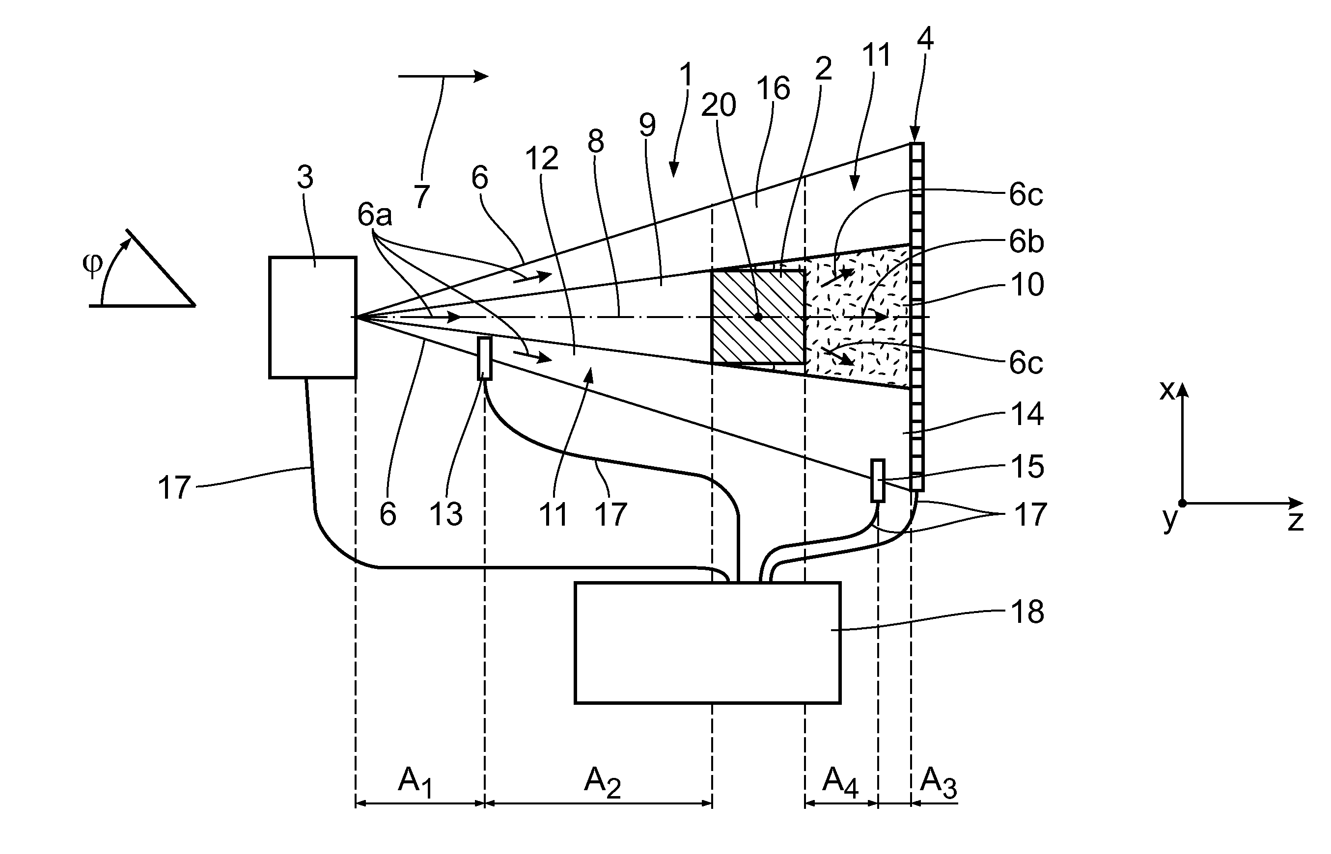
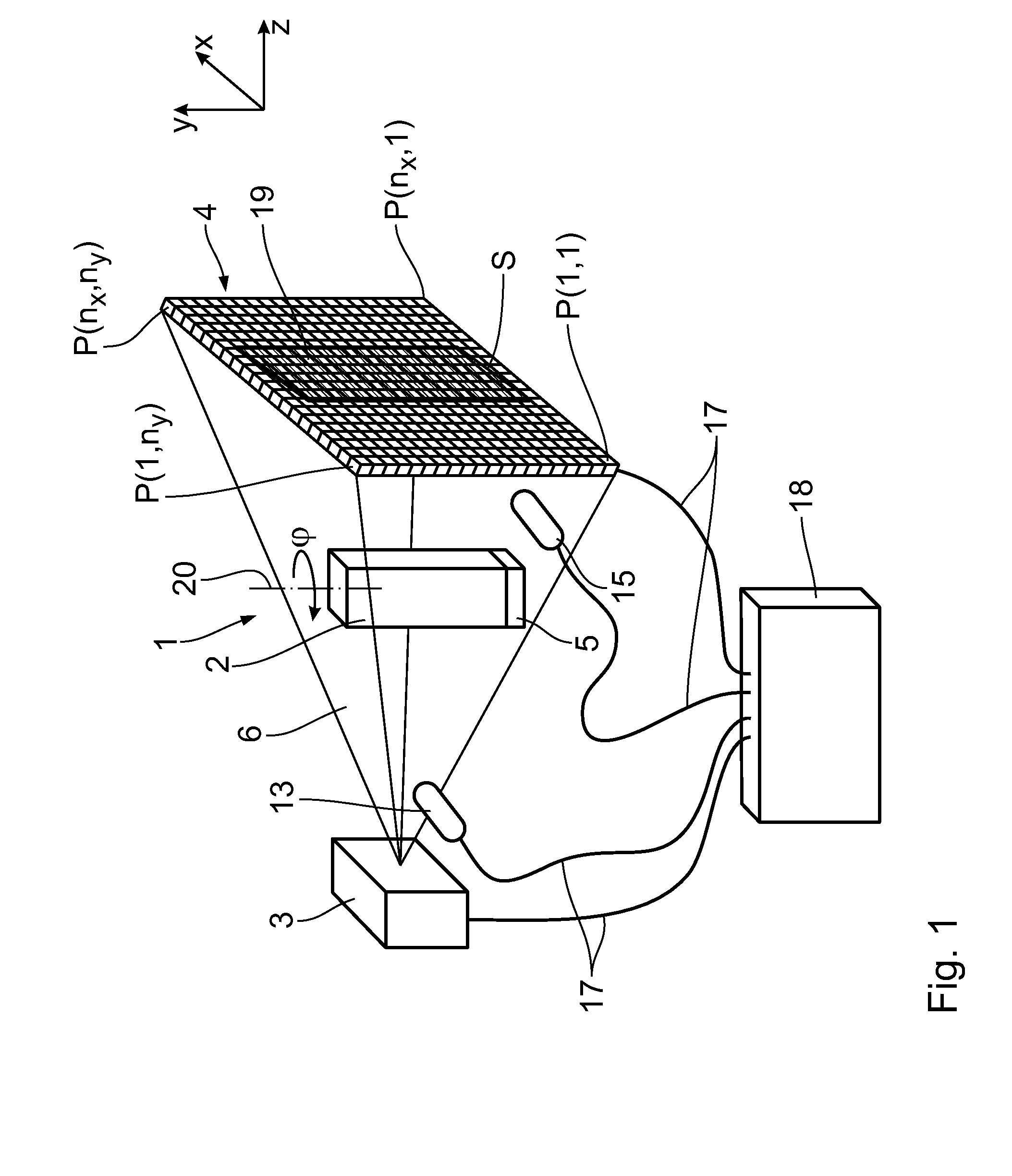
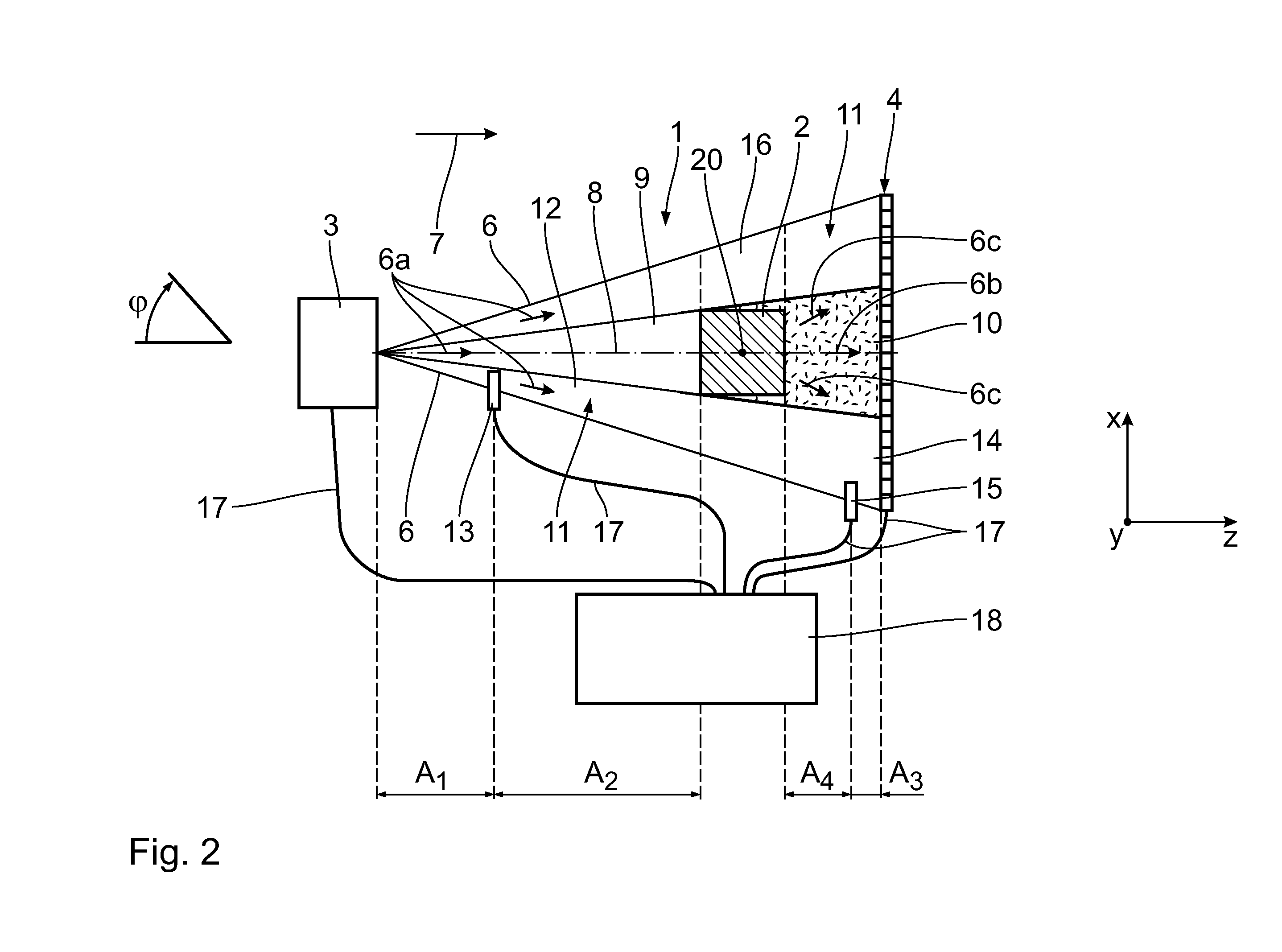
[0028]An X-ray computer tomograph 1, to investigate an object 2, has an X-ray source 3 and an associated X-ray detector 4. Arranged between the X-ray source 3 and the X-ray detector 4 is an object carrier 5, on which the object 2 can be positioned.

[0029]The X-ray source 3 is used to produce X-ray radiation 6 being emitted conically in a beam direction 7. The beam direction 7 runs substantially parallel to a center longitudinal axis 8 of the X-ray computer tomograph 1. The X-ray source 3 is, for example, configured as an X-ray tube, the structure of which is known.

[0030]The X-ray detector 4 extends substantially in an x-y plane, which is defined by an x-direction and a y-direction extending perpendicular thereto. The center longitudinal axis 8 defines a z-direction, which runs substantially perpendicular to the x-y plane. The X-ray detector 4, in the x- and y-direction, has a large number of pixels, which are individually called P(x,y), wherein x=1 to nx and y=1 to ny. The X-ray dete...


PUM

PropertyMeasurementUnit
axial distanceaaaaaaaaaa
CTaaaaaaaaaa
distanceaaaaaaaaaa

Abstract

In an X-ray computer tomograph and a method for investigating an object by means of X-ray computer tomography, to improve the image quality, a first intensity of the X-ray radiation between an X-ray source and the object is measured by means of a first intensity measurement device (13) and a second intensity of the X-ray radiation between the object and the X-ray detector outside a projection region of the object is measured by means of a second intensity measurement device. A scattered radiation correction factor is calculable by means of the measured intensities to reduce the scattered radiation.

Description

CROSS REFERENCE TO RELATED APPLICATIONS[0001]This application is a United States National Phase application of International Application PCT / 2009 / 001325 and claims the benefit of priority under 35 U.S.C. §119 of German patent application DE 10 2008 011 391.3 filed Feb. 28, 2008, the entire contents of which are incorporated herein by reference.FIELD OF THE INVENTION[0002]The invention relates to an X-ray computer tomograph for investigating an object by means of X-ray computer tomography comprising an X-ray source for generating X-ray radiation, an X-ray detector for detecting the X-ray radiation, an object carrier for positioning an object to be investigated between the X-ray source and the X-ray detector, and an evaluation unit for evaluating the detected X-ray radiation. The invention furthermore relates to a method for investigating an object by means of X-ray computer tomography comprising the steps of positioning an object to be investigated between an X-ray source and an X-ra...

Claims


Application Information

Patent Timeline
Patent Type & Authority Applications(United States)
IPC IPC(8): G01N23/04
CPCG01N2223/419G01N23/046
Inventor FUCHS, THEOBALDUHLMANN, NORMAN
Owner FRAUNHOFER GESELLSCHAFT ZUR FOERDERUNG DER ANGEWANDTEN FORSCHUNG EV
Why Eureka
Try Eureka