
Image decoding apparatus and control method for the same

a decoding apparatus and image technology, applied in the field of decoding techniques for encoded image data, can solve the problems of delay in display, double or more calculation cost of stream conversion processing, and much lower resolution of display devices used in personal computers and the like, so as to speed up decoding processing and reduce the influence of omission of processes on image quality

Active Publication Date: 2010-12-16
CANON KK
View PDF62 Cites 5 Cited by
  • Summary
  • Abstract
  • Description
  • Claims
  • Application Information

AI Technical Summary

Benefits of technology

[0007]The present invention therefore provides a technique of speeding up decoding processing by omitting several processes while reducing the influence of omission of processes on image quality in accordance with the variable magnification ratio at which an image is to be decoded and displayed.
[0015]According to the present invention, it is possible to speed up decoding processing by omitting several processes while reducing the influence of omission of processes on image quality in accordance with the variable magnification ratio at which an image is to be decoded and displayed.

Problems solved by technology

Although this function can suppress distortion, the calculation cost for stream conversion processing increases double or more.
A decoding apparatus, which decodes data encoded upon distortion suppression, always needs to perform a process corresponding to distortion processing, resulting in a delay in display, no matter how the user wants to display the data at high speed.
However, display devices used in personal computers and the like have much lower resolutions than digital cameras.

Method used


Image

  • Image decoding apparatus and control method for the same
  • Image decoding apparatus and control method for the same
  • Image decoding apparatus and control method for the same

Examples


first embodiment

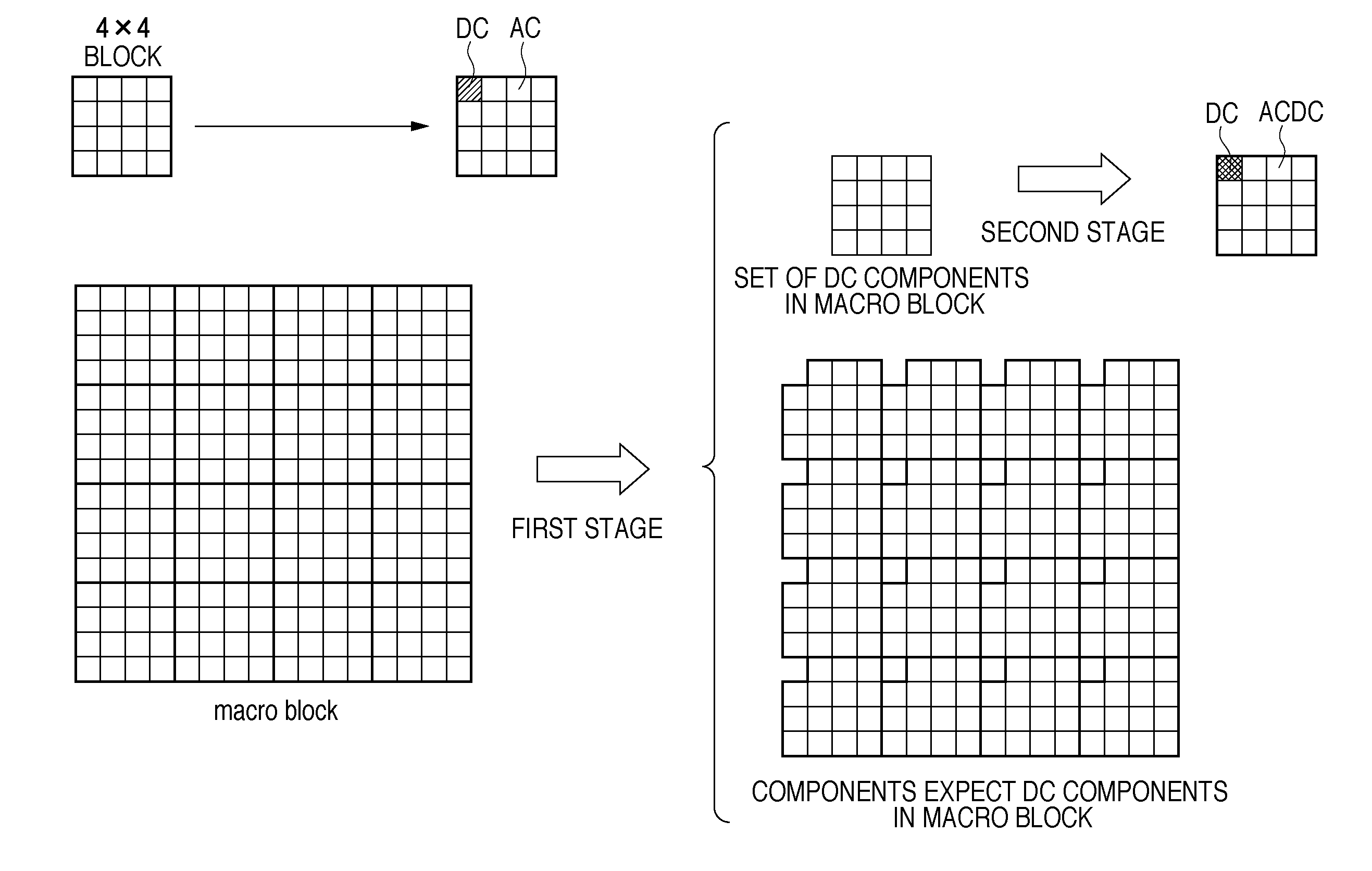
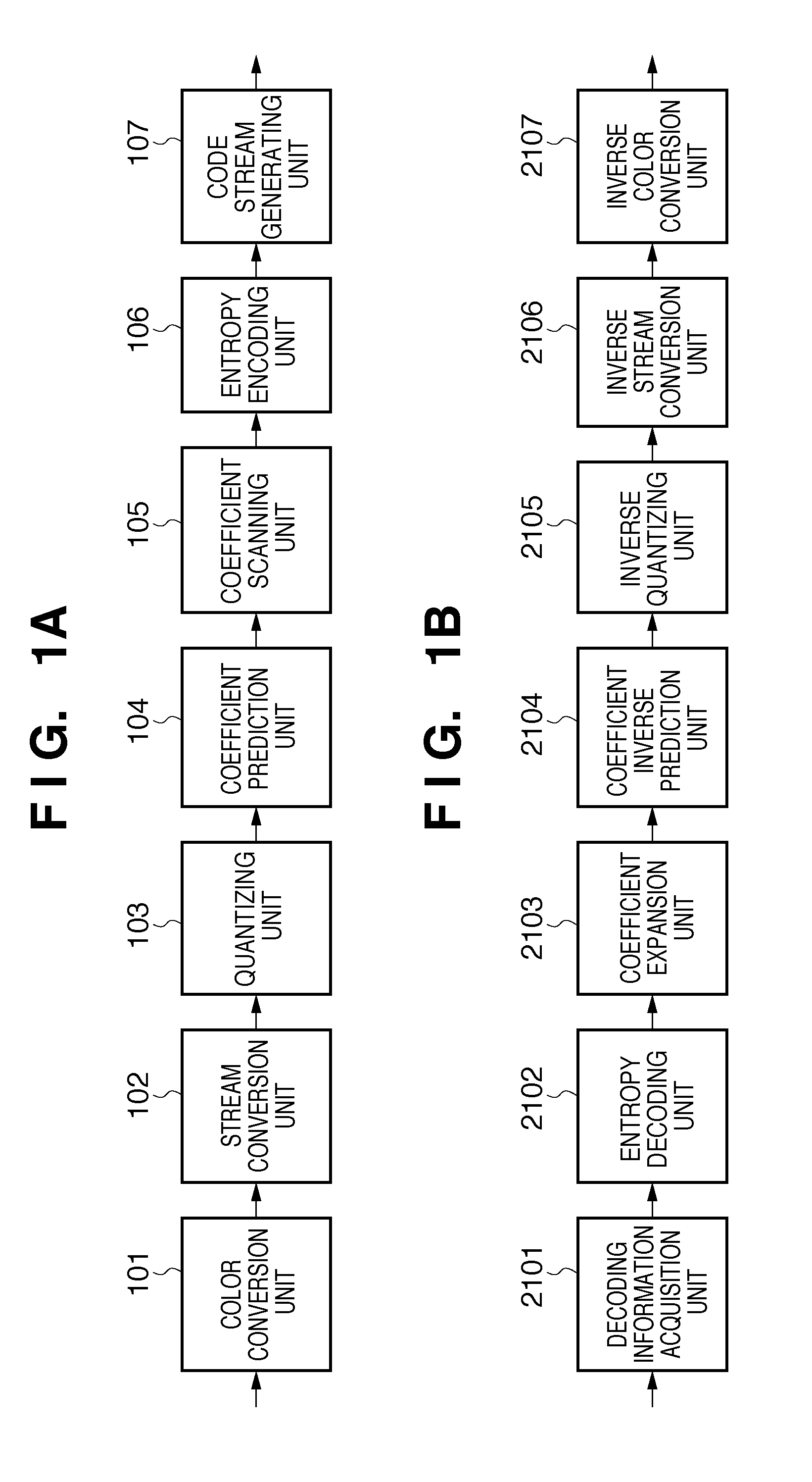
[0042]The technique (JPEG XR) based on reference 1 described above and the like has a block distortion suppression function used in encoding. The suppression processing is optional. That is, the user can designate one of the following three options: (1) perform no processing; (2) perform processing once before first stream conversion; and (3) perform processing once before first stream conversion, and once before second stream conversion. Option (1) allows high-speed encoding and decoding without any distortion suppressing effect. Option (3) provides a strong distortion suppressing effect, even though the encoding and decoding speeds are low. Option (2) comes between option (1) and option (3) in terms of effects. FIG. 22A shows a summary of the above description. Referring to FIG. 22A, “PCT” indicates stream conversion (frequency conversion) processing, and “POT” indicates distortion suppression processing.

[0043]Decoding processing is inverse to encoding processing. In general, ther...

second embodiment

[0150]The first embodiment has exemplified the method in the processing of performing frequency conversion (PCT processing) 0, 1, or 2 times at the time of encoding and decoding. The second embodiment will exemplify a case in which frequency conversion is performed once at the time of encoding and decoding, and block overlap processing (POT processing) is performed 0 or 1 times.

[0151]The apparatus arrangement of the second embodiment is the same as that of the first embodiment except for the above point. For this reason, the difference between the embodiments will be described below. A storage device in the second embodiment determines a variable magnification ratio R by using only one threshold Th1 (Th1=½ in FIG. 23B) when image data is decoded and displayed, as shown in FIG. 23B.

[0152]At the time of decoding, if the variable magnification ratio R designated by the user is larger than the threshold Th1, setting distortion suppression processing to “non-execution” will make distorti...

third embodiment

[0155]The second embodiment has exemplified the method providing one threshold Th1. However, it is possible to provide another threshold Th2 to perform a processing procedure for enlarging DC components. In the second embodiment, it is possible to fix r=½ in accordance with changes in resolution by ½ at a time as in JPEG2000 and the like. In this case, when decoding an image with ½ resolution, it is possible to perform level correction processing instead of inverse processing. The second embodiment has exemplified the case in which block overlap processing is always performed at the time of encoding. However, it is possible to provide this function as an optional function. Although the embodiment has exemplified the method of suppressing block-like distortion by performing block overlap processing, it is possible to use methods using various types of filters which are not applied across blocks. Although the method of correcting a dynamic range has been described, the present inventi...


PUM


Abstract

This invention provides a technique of speeding up decoding processing by omitting several processes while reducing the influence of omission of processes on image quality in accordance with the variable magnification ratios at which images are to be decoded and displayed. For this purpose, an apparatus according to the invention analyzes the header of decoding target encoded image data. The apparatus then obtains information indicating how many times distortion suppression processing has been executed at the time of the generation of the encoded image data. The apparatus decides which process can be omitted, based on the set variable magnification ratio and the information extracted from the header, and generates an image on which an output is based, by executing the processes which are not to be omitted. The apparatus then re-sizes the image in accordance with the set magnification ratio.

Description

BACKGROUND OF THE INVENTION[0001]1. Field of the Invention[0002]The present invention relates to a decoding technique for encoded image data.[0003]2. Description of the Related Art[0004]An encoding technique for image compression for a reduction in file size is indispensable for efficiently storing, managing, and transferring digital images. In general, when image data is to be encoded, the image is divided into several blocks, and encoding processing is performed on a block basis. When encoding is performed on a block basis, block boundaries tend to distort. Under the circumstance, an encoding technique that suppresses distortion at block boundaries is known (for example, Japanese Patent Laid-Open No. 2006-197573 to be referred to as reference 1 hereinafter). The technique disclosed in reference 1 divides an image into tiles. The technique then generates hierarchical stream data by repeating DCT for each tile. In order to suppress block distortion that occurs between tiles, this te...

Claims


Application Information

Patent Timeline
IPC IPC(8): G06K9/36H03M7/30H04N1/41H04N19/44H04N19/57H04N19/60H04N19/86H04N19/91
CPCH04N19/105H04N19/70H04N19/46H04N19/60H04N19/593H04N19/156H04N19/164H04N19/44H04N19/59
Inventor KISHI, HIROKI
Owner CANON KK
Learn More